Vibration wave driving apparatus
a driving apparatus and vibration wave technology, applied in the direction of piezoelectric/electrostrictive/magnetostrictive devices, piezoelectric/electrostriction/magnetostriction machines, electrical apparatus, etc., can solve the problems of difficult to provide the frictional surfaces of the ultrasonic vibrator b>3/b> and the driven body b>4, and achieve the effect of stable contact state and increase in the number of components
- Summary
- Abstract
- Description
- Claims
- Application Information
AI Technical Summary
Benefits of technology
Problems solved by technology
Method used
Image
Examples
embodiment 1
[0098]As Embodiment 1 is described an exemplary configuration of a vibration wave driving apparatus to which the present invention is applied.
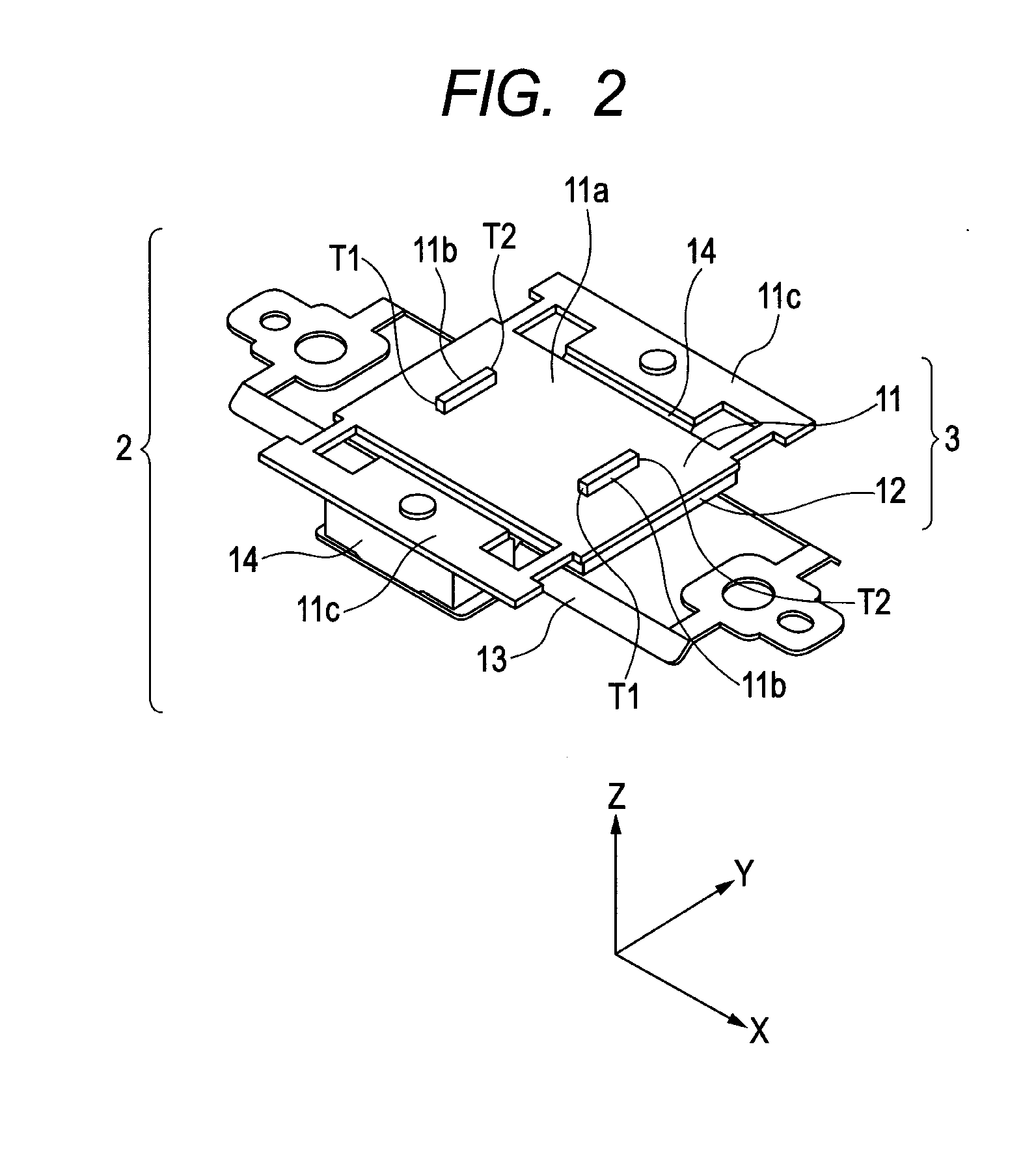
[0099]The vibration wave driving apparatus of the present embodiment includes a vibrator including a vibration body having a frictional surface and an electrical-mechanical energy conversion element, and a driven body which has a frictional surface having contact with the frictional surface of the vibrator and which is configured to be pressed through the respective frictional surfaces.
[0100]Further, the vibration wave driving apparatus is configured so that the driven body is relatively moved by elliptic motion of the vibrator through those respective frictional surfaces.
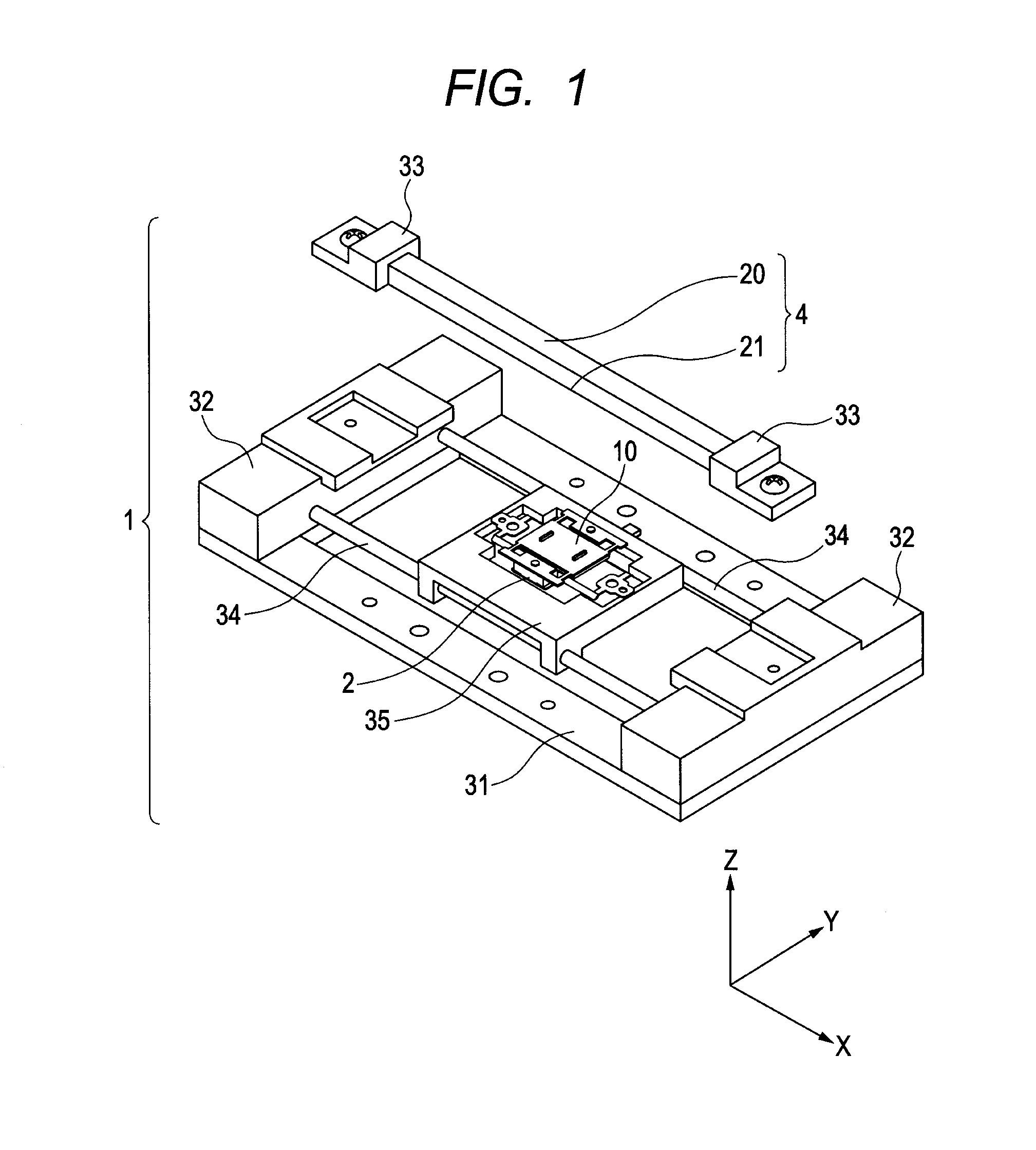
[0101]More specifically, as shown in FIG. 1, a vibration wave driving apparatus 1 of the present embodiment is configured as an apparatus which includes what is called an ultrasonic motor as a driving force and which performs linear driving with one degree of freedom.
[0102]As...
embodiment 2
[0162]As Embodiment 2, the following describes an exemplary configuration of a vibration wave driving apparatus having a different configuration from that in Embodiment 1, with the use of FIGS. 8A to 8B.
[0163]FIG. 8A shows a perspective view of a supporting member 13 in the present embodiment.
[0164]A vibration wave driving apparatus 1 in the present embodiment has the same configuration as in Embodiment 1 except the supporting member 13, and therefore the explanation that has been already given is omitted.
[0165]Even the supporting member 13 is the same as that explained in FIGS. 4A to 4C except some part, and therefore the explanation that has been already given is omitted.
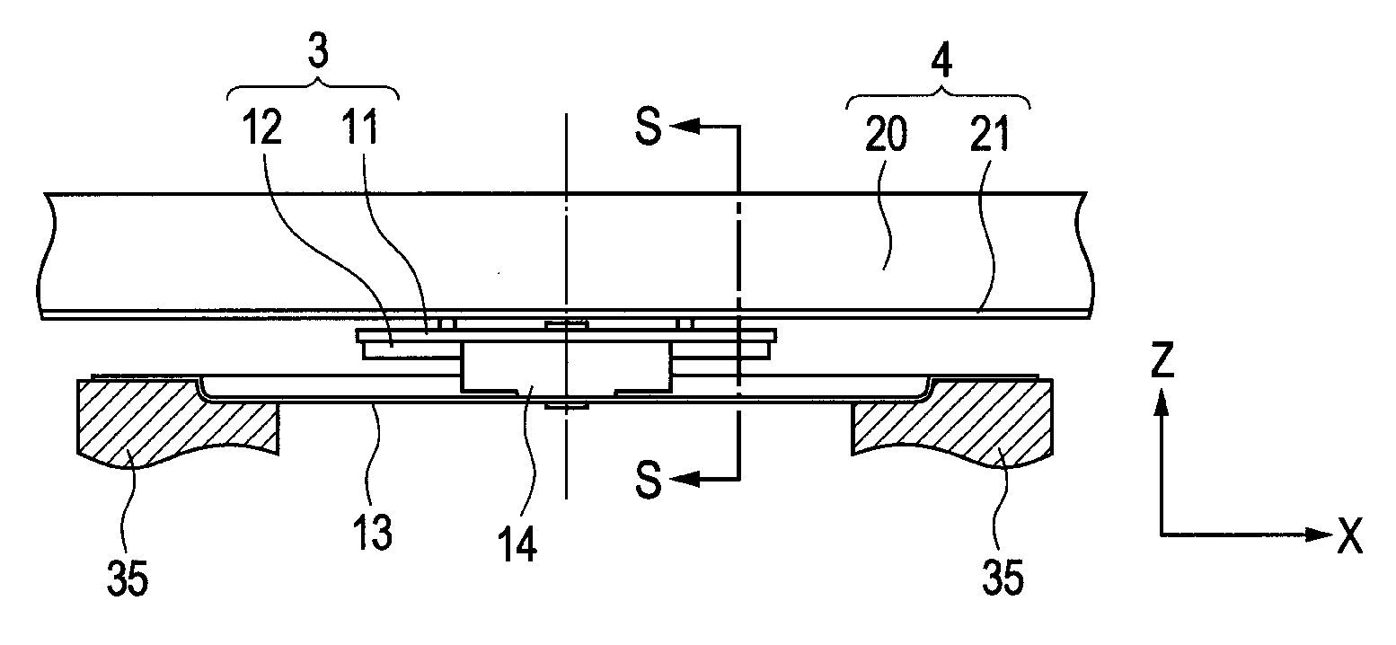
[0166]FIG. 8B shows a YZ cross section of elastically-deformable portions 13c taken along the position shown with reference signs S in FIG. 8A.
[0167]A reference sign C1 in the figure is the intersection (a rotation center of rotational deformation) of the extended lines of the cross sections of the elastically-def...
PUM
 Abstract
Description
Claims
Application Information
 - R&D
- Intellectual Property
- Life Sciences
- Materials
- Tech Scout
- Unparalleled Data Quality
- Higher Quality Content
- 60% Fewer Hallucinations
Browse by: Latest US Patents, China's latest patents, Technical Efficacy Thesaurus, Application Domain, Technology Topic, Popular Technical Reports.
© 2025 PatSnap. All rights reserved.Legal|Privacy policy|Modern Slavery Act Transparency Statement|Sitemap|About US| Contact US: help@patsnap.com


