
Method and apparatus for simulating head impacts for helmet testing

a head impact and helmet technology, applied in the direction of material strength testing goods, applications, and single impulsive force, can solve the problems of not being properly accounted for in present helmet standards and certification, not being protected from concussion injuries

Active Publication Date: 2012-10-04
KIS JR MIHALY +3
View PDF5 Cites 16 Cited by
  • Summary
  • Abstract
  • Description
  • Claims
  • Application Information

AI Technical Summary

Benefits of technology

[0011]In accordance with an aspect of the present invention, there is provided a method for testing a helmet, the method comprising: providing a head form adapted and constrained to rotate separately about a first axis of rotation and a second axis of rotation; generating a baseline rotational acceleration in relation to the first axis of the head form; generating a rotational acceleration in relation to the first axis when the helmet is installed on the head form; determining a degree of protection against rotational acceleration in relation to the first axis afforded by the helmet; generating a baseline rotational acceleration in relation to the second axis of the head form; generating a rotational acceleration in relation to the second axis when the helmet is installed on the head form; and determining a degree of protection against rotational acceleration in relation to the second axis afforded by the helmet.

Problems solved by technology

It has been recognized for some time that helmet testing has not taken rotational acceleration into account and that helmets may protect against certain types of severe injury but may not be protecting against concussive injury.
Science has found that a rotational force component is present in every impact but this is has not been properly accounted for in present helmet standards and certification.

Method used


Image

  • Method and apparatus for simulating head impacts for helmet testing
  • Method and apparatus for simulating head impacts for helmet testing
  • Method and apparatus for simulating head impacts for helmet testing

Examples


Embodiment Construction

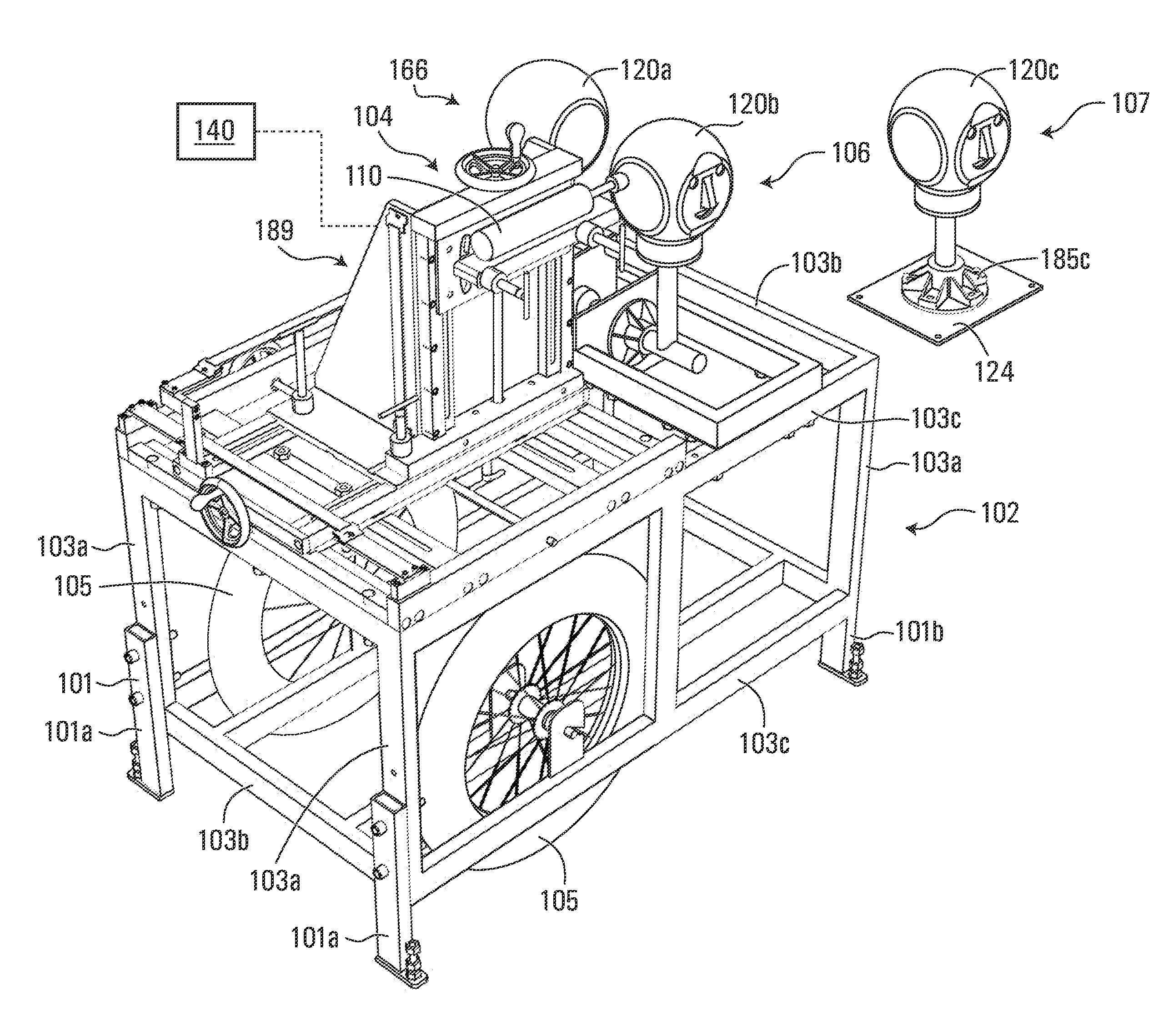
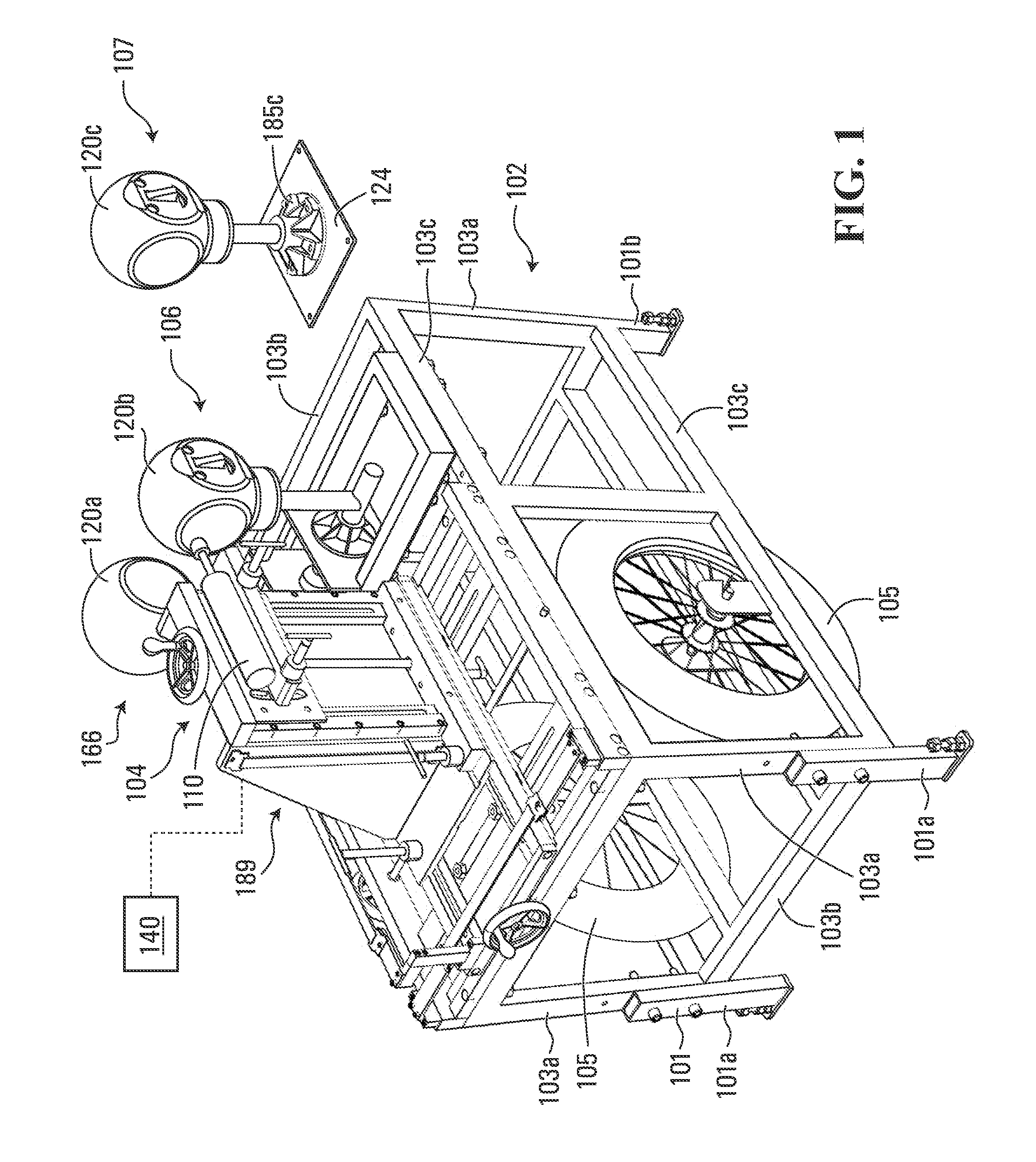
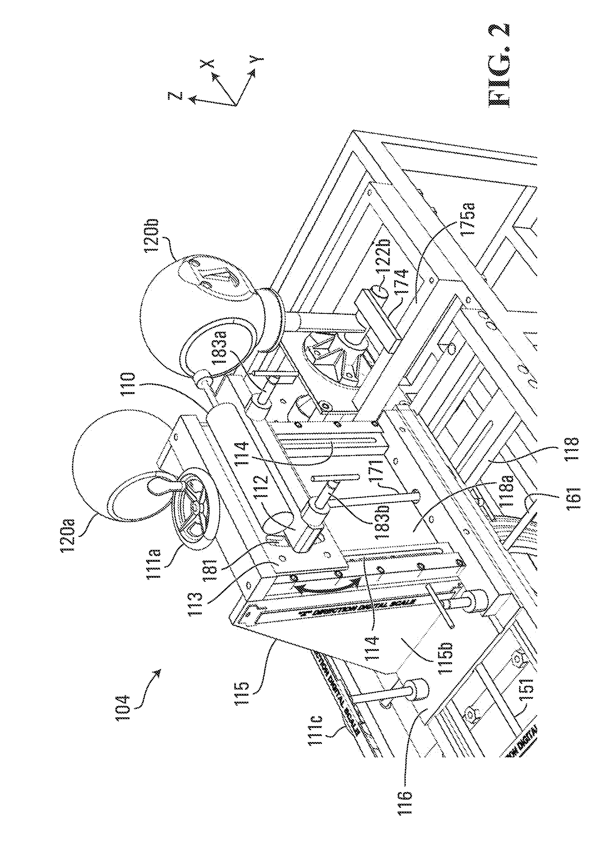
[0058]With reference to FIGS. 1-19 in which like reference designators refer to like elements, a test apparatus 100 exemplary of an embodiment of the present invention is shown in three configurations, wherein FIGS. 1-9 show apparatus 100 in a first configuration, FIGS. 10-14 show apparatus 100 in a second configuration, and FIGS. 15-19 show apparatus 100 in a third configuration.

[0059]As shown, test apparatus 100 may generally comprise a frame 102 formed of a plurality of support frame members 103 arranged substantially in a cuboid shape. Support frame members 103 may be made from one or more suitable materials such as a metal like steel or aluminium, so as to be able to withstand the loads generated by test apparatus 100. Also support members may include generally vertically oriented frame members 103a that are positioned to be able to also maintain test apparatus in a stable orientation and resist any significant movement while test apparatus 100 is being operated. Frame 102 may ...


PUM

PropertyMeasurementUnit
stroke lengthaaaaaaaaaa
massaaaaaaaaaa

Abstract

An apparatus is disclosed that includes a frame, an impact delivery unit for delivering an impact force and at least one head form. The head form is adapted to be mounted to the frame such that the impact delivery unit can deliver an impact force to a designated location on the head form. The head form is configured to have a helmet installed thereon. The head form is selectively rotatable about each of a plurality of different axes of rotation, wherein movement of the head form is constrained to be able to move only in rotation and in rotation about only one axis of rotation of the plurality of axes at any time. A measuring system provides an indicator of the rotational acceleration of the head form when rotated about each of the plurality of axes. Also disclosed are methods for comparing the degree of protection afforded by first and second helmets.

Description

FIELD OF THE INVENTION[0001]The present invention relates to a method and apparatus for simulating head impacts for helmet testing.BACKGROUND[0002]Various activities, such as for example contact sports or military operations, require the use of helmets to attempt to protect participants from injury to their heads due to impact forces that may be sustained during such activities. As helmets protect against head injury, it follows that the science of head injury should underlie the development and testing of helmets to achieve the greatest effectiveness.[0003]Concussion science is not well understood. Holborn, in 1943 and 1945, proposed rotational acceleration as the primary concussive mechanism. Gurdjian, Lissner, and others in the 1950's and 60's however thought that deformation of the skull and pressure waves that propogated through the cranial vault were the most offending agents. In the 1970's and 80's experiments by Gennarelli, Ommaya, Thibault, Adams and others produced head in...

Claims


Application Information

Patent Timeline
Patent Type & Authority Applications(United States)
IPC IPC(8): G01N3/30
CPCG01N3/30G01N2033/0086G01N2033/008A42B3/0433G01N33/008G01N33/0086G01M17/0078
Inventor KIS, JR., MIHALYKIS, SR., MIHALYSAUNDERS, FRASER WORDENTEN HOVE, MARTIN WILLIAM
Owner KIS JR MIHALY
Learn More