Stereo image capturing device, stereo image capturing method, stereo image display device, and program

a technology of stereo image and display device, which is applied in the field of stereo image capture device, stereo image capturing method, stereo image display device, program, etc., can solve the problem that the image is difficult to be perceived as a three-dimensional image by the two eyes

Inactive Publication Date: 2012-09-27
PANASONIC CORP
View PDF5 Cites 23 Cited by
  • Summary
  • Abstract
  • Description
  • Claims
  • Application Information

AI Technical Summary

Benefits of technology

[0059]The stereo image capturing method has the same advantageous effects as the stereo image capturing device of the first aspect of the present invention.
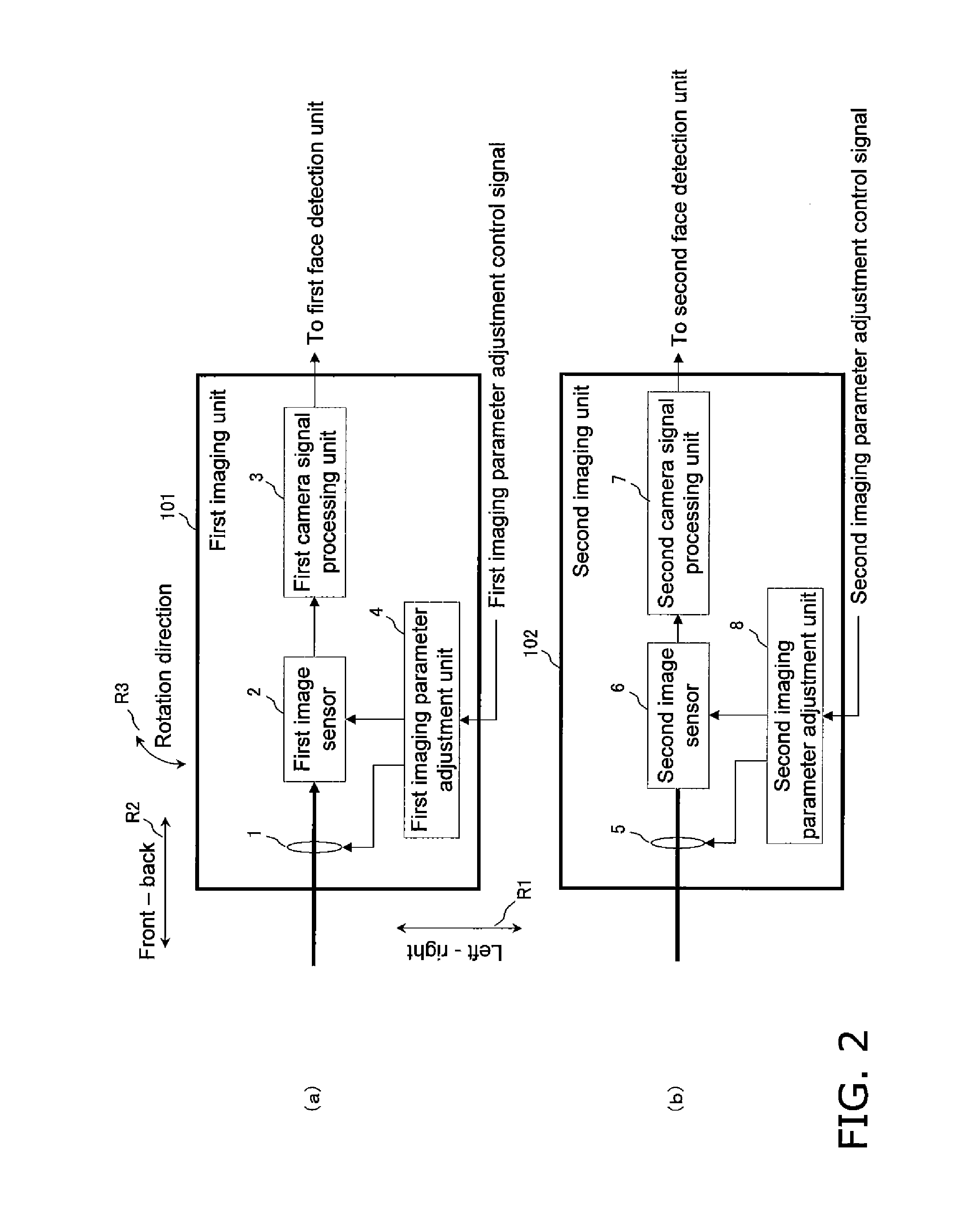
[0060]A thirteenth aspect of the present invention provides a program enabling a computer to implement a stereo image capturing method used by a stereo image capturing device including an imaging unit configured to capture an image of a subject and generate a first point image corresponding to a scene including the subject viewed from a first point and generate a second point image corresponding to a scene including the subject viewed from a second point different from the first point. The stereo image capturing method includes a subject detection process, a disparity detection process, a calculation process, a changing process, and an imaging process.
[0061]In the subject detection process, a first subject area is detected from the first point image, and a second subject area is detected from the second point image.
[0062]In the disparity detection process, disparity information indicating a binocular disparity between the first subject area included in the first point image and the second subject area included in the second point image is detected.
[0063]In the calculation process, an imaging parameter to be used in capturing the image of the subject is calculated using the disparity information detected in the disparity detection process.
[0064]In the changing process, the imaging parameter of the imaging unit is adjusted based on the imaging parameter calculated in the calculation process.

Problems solved by technology

Also, if the disparity on the display screen in FIG. 3C increases to a value exceeding the distance between the right eye and the left eye of a human (the distance of about 5 to 7 cm), the resulting image would be difficult to be perceived as a three-dimensional image by the two eyes.

Method used


Image

  • Stereo image capturing device, stereo image capturing method, stereo image display device, and program
  • Stereo image capturing device, stereo image capturing method, stereo image display device, and program
  • Stereo image capturing device, stereo image capturing method, stereo image display device, and program

Examples


first embodiment

Outline of First Embodiment

[0168]As described above, the stereo image capturing device 1000 of the present embodiment detects a face area in a stereo image (in each of a left eye image and a right eye image), and calculates the disparity (the disparity on the virtual (display) screen) using the detected face area (the face detection result). The stereo image capturing device 1000 then sets the imaging parameter in a manner that the subject will be placed at a predetermined placement position based on the disparity calculated to fall within an appropriate fusion area (for example, a stereoscopic-viewing enabling area). As a result, the stereo image capturing device 1000 captures (obtains) a stereo image having a stereoscopic effect or a depth intended by the photographer (the user) or a stereo image having an appropriate stereoscopic effect without an inappropriate viewing effect including a subject placed at an excessively forward position.

[0169]The stereo image capturing device 100...

second embodiment

Outline of Second Embodiment

[0244]As described above, the stereo image display device 2000 of the present embodiment performs face detection (subject detection) on the left and right display images forming the captured stereo image, and calculates the disparity using the face detection result (the subject detection result). The stereo image display device 2000 places the subject at a predetermined position (for example, at a position intended by the user) based on the calculated disparity, and displays a stereo image having an appropriate stereoscopic effect and an appropriate depth without an inappropriate viewing effect including a subject placed at an excessively forward position.

[0245]The image reproduction unit 301 is an example of an image reproduction unit.

[0246]The first subject detection unit 304 and the second subject detection unit 305 each are an example of a subject detection unit.

[0247]The disparity detection unit 306 is an example of a disparity detection unit.

[0248]T...


PUM


Abstract

A conventional device adjusts the convergence angle of its imaging unit in a manner that the left-and-right face detection areas are at the same coordinates and thus forms a stereo image that will be placed on a display screen during display, but fails to place a subject at an intended stereoscopic position. A stereo image capturing device (1000) detects a face area from a right image, detects a disparity using the left-and-right face areas, and sets the imaging parameters (the subject distance, focal length, stereo base, and convergence angle) to adjust the detected disparity to a disparity enabling the subject to be placed at an intended placement position. This device forms a stereo image having an appropriate stereoscopic effect in which a target subject is placed at an intended stereoscopic position. The device uses only a limited target area for face detection and thus requires less calculation for face detection.

Description

TECHNICAL FIELD[0001]The present invention relates to an image capturing device (a stereo image capturing device) that captures a right eye image and a left eye image for stereoscopic viewing, a display device for displaying a right eye image and a left eye image captured for stereoscopic viewing, and a method, a program, and an integrated circuit used in such an image capturing device and in such a display device.BACKGROUND ART[0002]When a stereo image (a three-dimensional image) of a subject is captured using a left eye camera and a right eye camera and is displayed by a display device, the subject is placed at a position that can vary depending on a disparity between the right and left images on the display screen.[0003]FIGS. 3A to 3C are diagrams each describing the placement position of the subject. FIG. 3A shows the subject placed in front of the display screen (placed at a forward position from the display screen). FIG. 3B shows the subject placed at the display screen (place...

Claims


Application Information

Patent Timeline
Patent Type & Authority Applications(United States)
IPC IPC(8): H04N13/02H04N13/04
CPCH04N13/0022H04N13/0296H04N13/0239H04N13/128H04N13/239H04N13/296
Inventor TSUDA, KENJIROSHIMAZAKI, HIROAKIJURI, TATSUROONO, HIROMICHI
Owner PANASONIC CORP
Why Eureka
Try Eureka