
Lens connection module and connection adapter for same

a technology of connection module and lens, which is applied in the direction of mounting, camera body details, instruments, etc., can solve the problems of inconvenience in user's operation, inapplicability to significant zoom-in or zoom-out landscape photography, and overly long time, so as to improve the complexity of the joint structure, increase the flexibility of application, and allow the utilization of a conventional lens

Inactive Publication Date: 2012-09-20
LUMOS TECH
View PDF5 Cites 13 Cited by
  • Summary
  • Abstract
  • Description
  • Claims
  • Application Information

AI Technical Summary

Benefits of technology

[0008]An objective of the invention is to provide a lens connection module magnetically engageable with an image capture device, thereby realizing simple combination and detachment and further facilitating convenience in product usage.
[0009]Another objective of the invention is to provide a lens connection module using a simple structure of magnetic attraction to an image capture device, thereby simplifying the module structure and reducing manufacture cost.
[0010]Yet another objective of the invention is to provide a lens connection module using an asymmetric structure for joint to an image capture device, thereby effectively eliminating the problem of erroneous installation direction.
[0013]To increase application flexibility and allow utilization of a conventional lens, a connection adapter is further described below. The connection adapter is adapted for being magnetically mounted on an image capture device. The image capture device is formed with a light entry opening and provided with a first ferromagnetic unit. The connection adapter is also adapted for mounting an external lens in front of the light entry opening of the image capture device. The connection adapter comprises a base unit, comprising a joint face for facing toward the light entry opening, wherein the base unit includes a pathway wall which defines a light collecting pathway and adapted to engage the external lens; and a second magnetic unit, mounted on the base unit and adapted to magnetically connect the joint face to the first ferromagnetic unit.
[0014]Through the aforementioned structure, the invention improves complicated joint architecture and tedious un-installation steps, thus allowing simplified use and structure cost reductions, and providing a foolproof design for further preventing installation angle deviation from expectation as well. By using magnetic attraction, the joint and detachment operations of the lens connection module according to the invention and an image capture device become relatively convenient, so manufacture costs can be saved and the user can easily complete installation and un-installation processes with one hand thus practically elevating the integral performance.

Problems solved by technology

Typically, the zoom adjustment in this type of image capture devices spans at most approximately a range of ten something folds, which supports only image shooting for general views, but not applicable for significant zoom-in or zoom-out landscape photography.
However, as the advent of digital cameras and mobile phones, differences indeed exist in various product specifications no matter with regards to lens diameter, lens retraction, lens configuration / profile or other aspects, so it is inevitable to be confronted with difficulties in, upon using digital cameras and mobile phones of different specifications, how to, on one hand, make the lens connection module conform to various specifications and, on the other hand, to facilitate simple attachment / detachment with assured joint robustness.
That is, with one hand fixedly holding on the lens of the single lens camera, the other hand rotates the filter or other peripheral equipment, which is obviously not handy enough and may take overly long time to complete such relative rotations thus causing inconvenience in user's operation.

Method used


Image

  • Lens connection module and connection adapter for same
  • Lens connection module and connection adapter for same
  • Lens connection module and connection adapter for same

Examples


Embodiment Construction

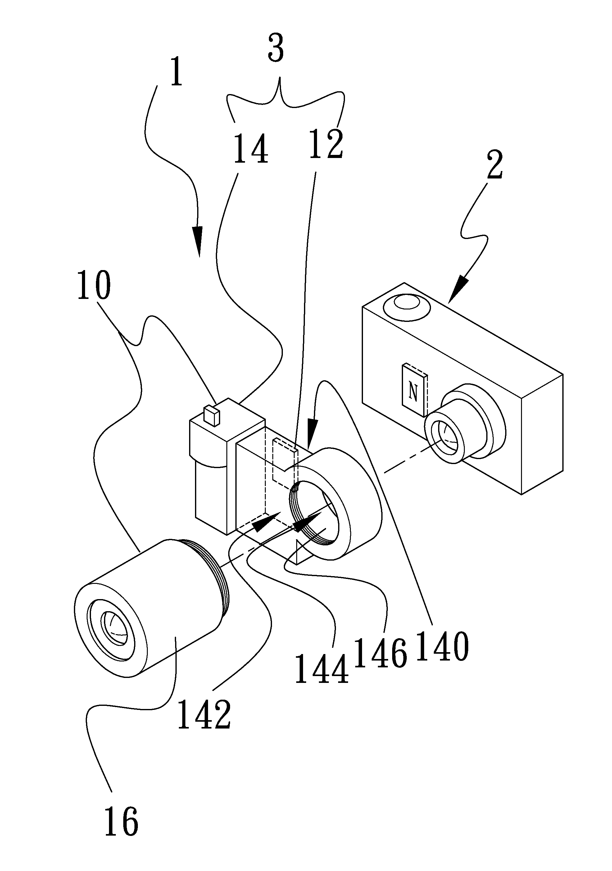
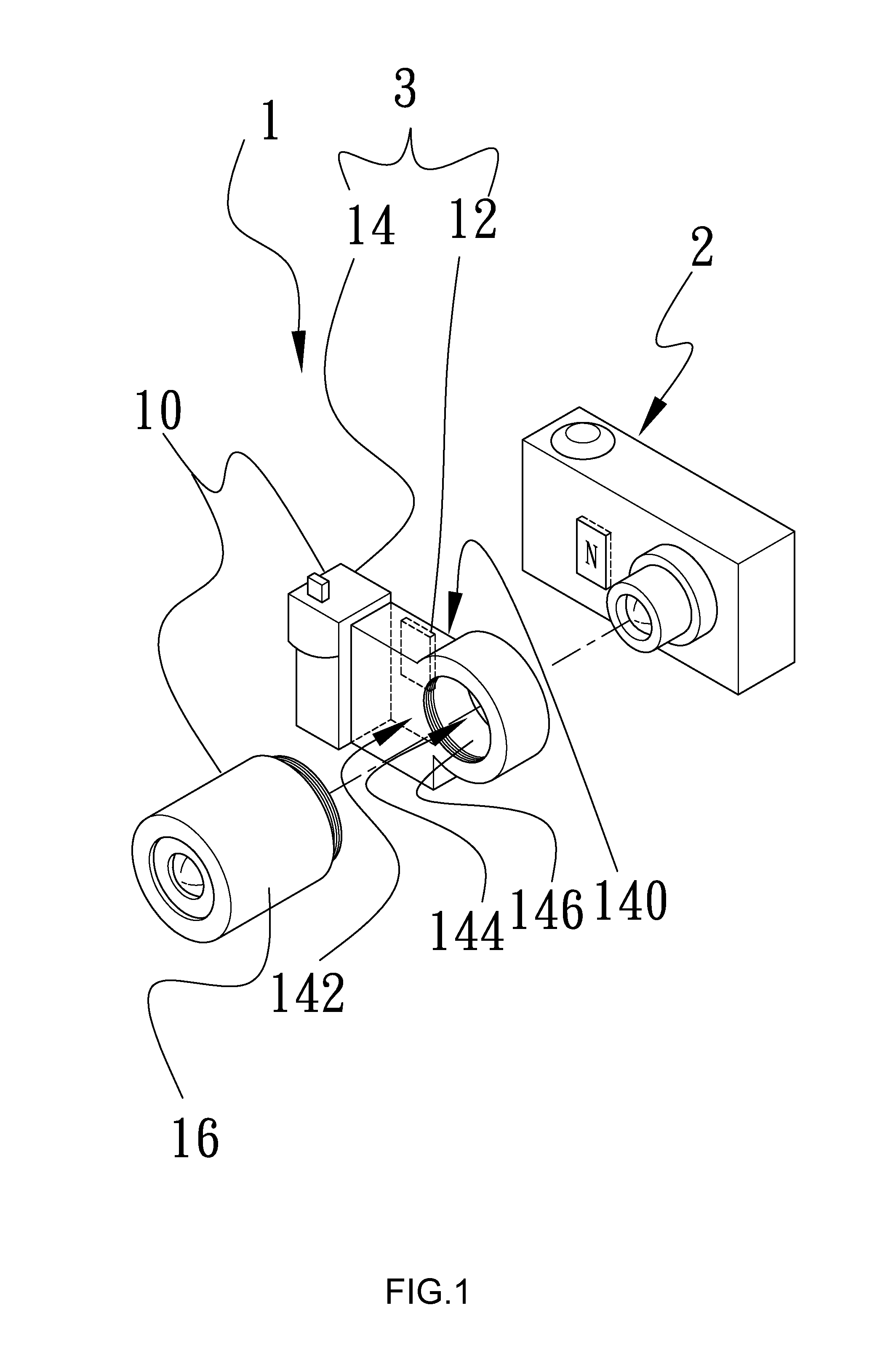
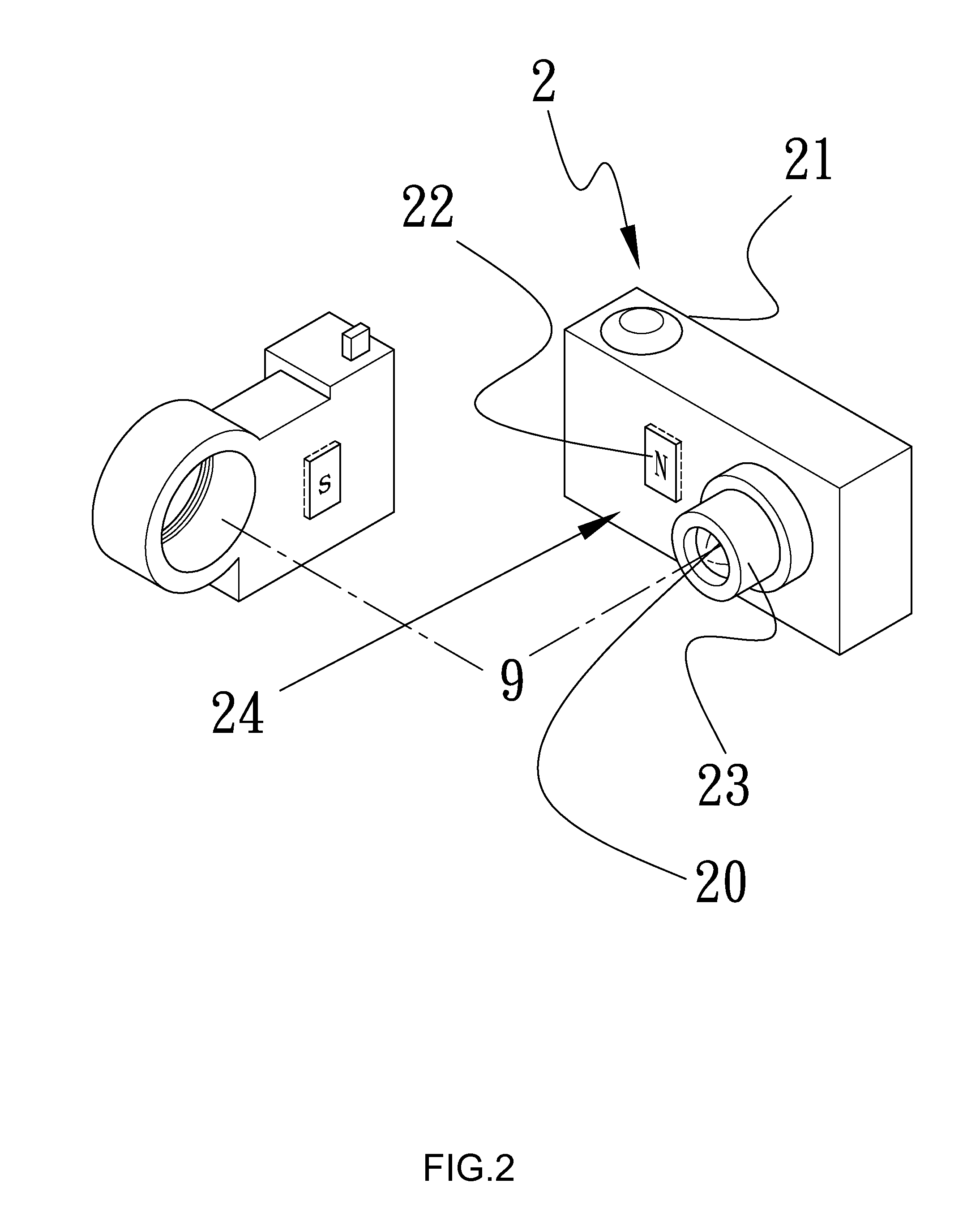
[0022]For illustrative purpose, the first preferred embodiment according to the invention as shown in FIGS. 1, 2 and 3 takes a digital camera 2 as an example of the image capture device. The digital camera 2 includes a front face 24 from which the lens protrudes, and the front side of the lens is defined as a light entry opening 20. The lens connection module 1 comprises a lens connection body 10 and a second magnetic unit 12 exemplified as a piece of strong magnet. The lens connection body 10 can be further divided into a base unit 14 and an external lens 16. The base unit 14 includes a joint face 140 facing toward of the front face 24 of the image capture device 2, while a light entry face 142 opposite to the joint face 140 for assembly with the external lens 16.

[0023]To allow entry of external image light beams into the image capture device 2 through the external lens 16, the base unit 14 has a light collecting pathway 144 penetrating through the joint face 140 and the light entr...


PUM


Abstract

A lens connection module is disclosed, which can be magnetically installed on an image capture device having a light entry opening and a first magnetic unit, and comprises a lens connection body and a second magnetic unit installed on the lens connection body for magnetically connecting to the first magnetic unit. The lens connection body includes a light collecting pathway corresponding to the light entry opening and extending along a light axis, the first magnetic unit has at least one ferromagnetic component arranged on the front face in a radially asymmetric manner, and the second magnetic unit has a magnetic component corresponding to the ferromagnetic component and installed on a joint face. As such, the lens connection module allows quick installation onto and detachment from the image capture device, thereby increasing application flexibility and operation convenience of the image capture device.

Description

BACKGROUND OF THE INVENTION[0001]1. Field of the Invention[0002]The present invention generally relates to a lens connection module and a connection adapter for the same. In particular, the invention relates to a lens connection module magnetically installed on an image capture device and a connection adapter for the same.[0003]2. Description of Related Art[0004]As digital cameras and mobile phones provide features like immediate image preview and easy exportation to computer-related devices, they have been quickly replacing conventional film cameras and become the mainstream on current camera market. Typically, the zoom adjustment in this type of image capture devices spans at most approximately a range of ten something folds, which supports only image shooting for general views, but not applicable for significant zoom-in or zoom-out landscape photography. To resolve these issues, it is quite often to externally connect a high magnification lens, a micro-lens or a short-range light...

Claims


Application Information

Patent Timeline
IPC IPC(8): G02B7/02
CPCG02B7/022G03B17/565G03B17/12G02B7/14
Inventor YANG, CHIH-YI
Owner LUMOS TECH
Learn More