
Vibration Isolation Brackets for Roller Blinds

Inactive Publication Date: 2012-09-13
NG PHILIP +1
View PDF14 Cites 4 Cited by
  • Summary
  • Abstract
  • Description
  • Claims
  • Application Information

AI Technical Summary

Benefits of technology

[0004]In accordance with one aspect of the present invention, there is provided a support for mounting an end of a roller blind to a structure such as a wall, ceiling and window frame. The support includes a first plate for mounting to the end of the roller blind and a second plate adjacent the first plate. The second plate has a central aperture dimensioned to receive the end of the roller blind. The support further includes a bracket for mounting the second plate to the structure. A plurality of vibration absorbing fasteners are provided for mounting the first plate to the second plate and dampening vibrations travelling from the first plate to the second plate.

Problems solved by technology

While this combination of support brackets, control mechanisms and idle ends have been used quite successfully for several decades, there is one problem generally associated with this combination.
While this is often of little concern in hand operated roller blinds, electric powered roller blinds can generate annoying vibrations which translate into unpleasant noise when the blind is operated.

Method used


Image

  • Vibration Isolation Brackets for Roller Blinds
  • Vibration Isolation Brackets for Roller Blinds
  • Vibration Isolation Brackets for Roller Blinds

Examples


Embodiment Construction

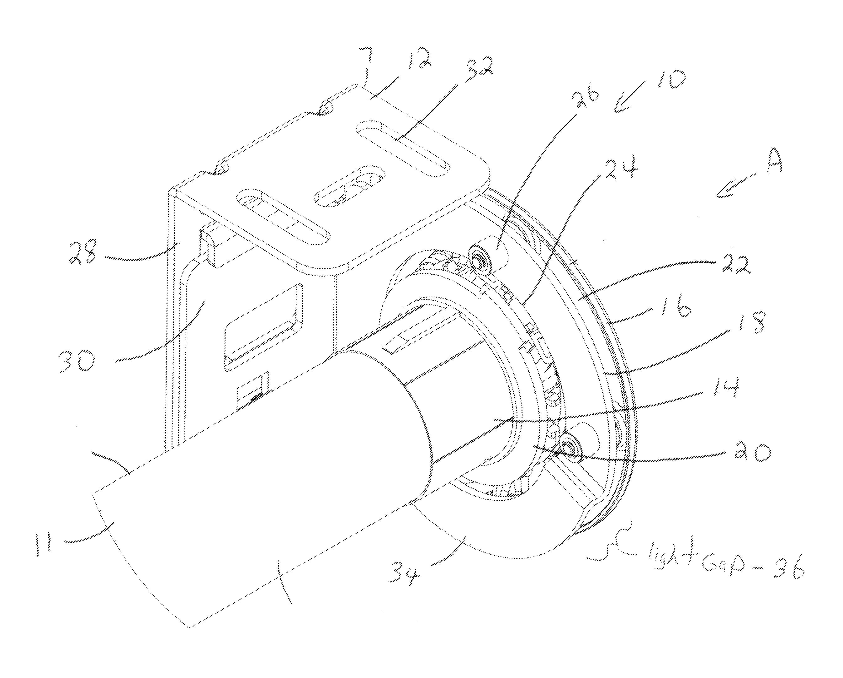
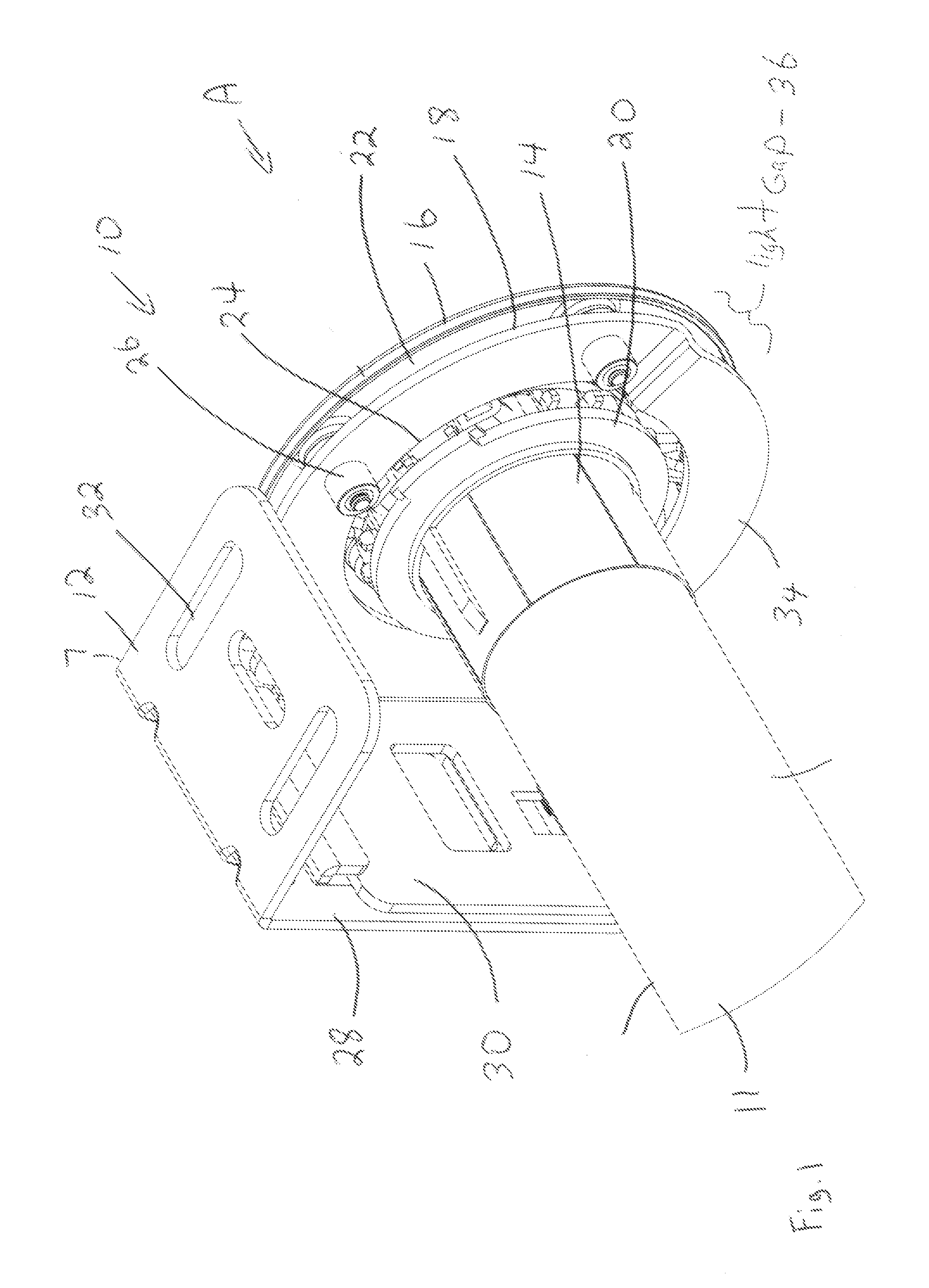
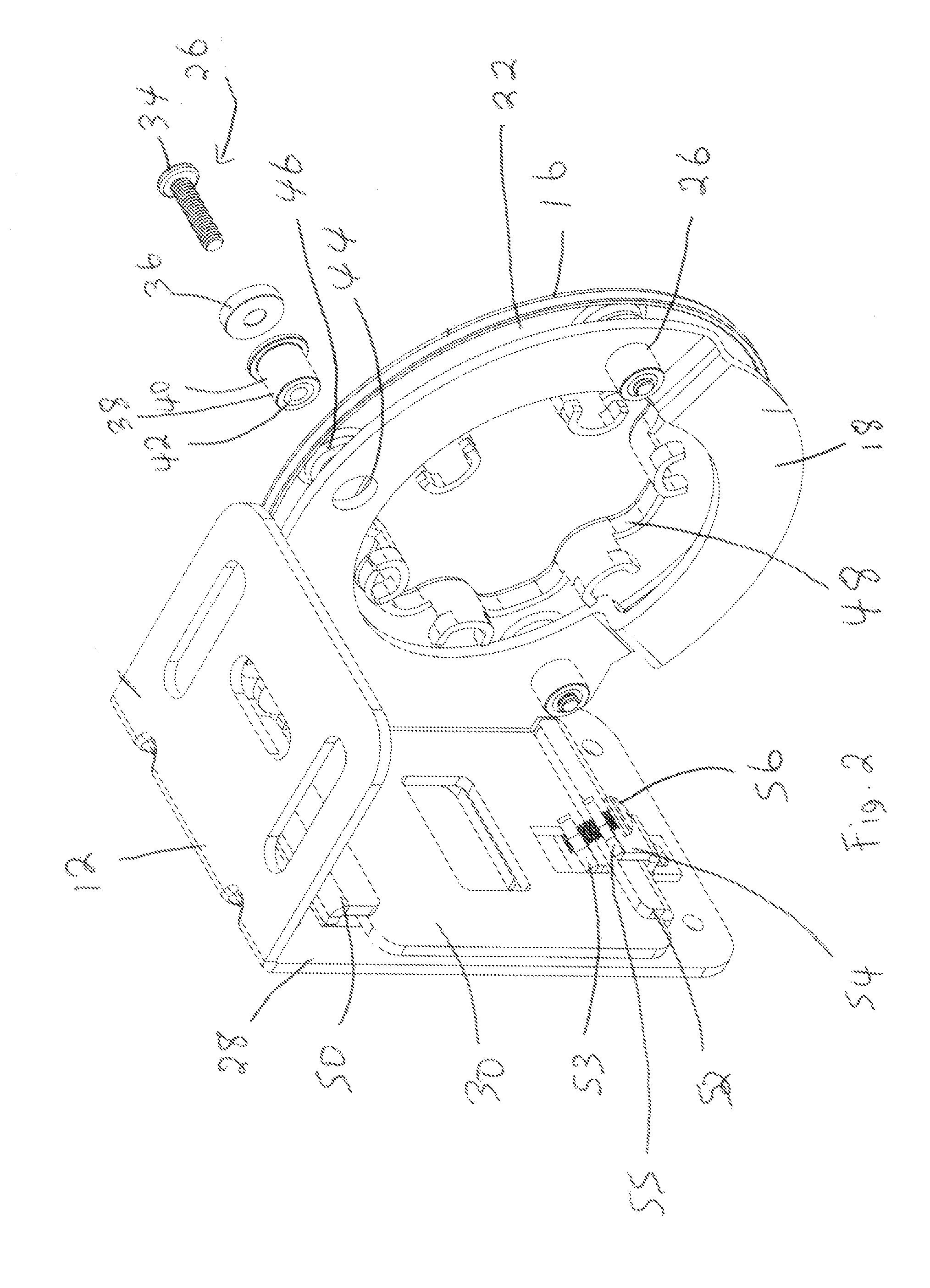
[0011]Referring to FIG. 1, a support made in accordance with the present invention is shown generally as item 10 and includes mounting bracket 12, first plate 16, and second plate 18. Roller blind 9 includes an electric motor drive 11 which is coupled to roller control mechanism 14. Control mechanism 14 is coupled to the roller tube (not shown) by fitting the control mechanism within one end of the roller tube. Control mechanism 14 has a sprocket portion 20 which can be used with a roller chain (not shown) for operating the control mechanism without the electric drive motor. Control mechanism 14 passes through aperture 24 in second plate 18 and is mounted directly to first plate 16. Plates 16 and 18 are parallel to each other and separated by gap 22. The first and second plates are connected to each other by vibration dampening fasteners 26. Second plate 18 has a transverse tongue 30 extending perpendicularly from the rest of the plate. Tongue 30 is mounted to back wall 28 of bracke...


PUM


Abstract

There is disclosed a support for mounting an end of a roller blind to a structure such as a wall, ceiling and window frame. The support includes a first plate for mounting to the end of the roller blind and a second plate adjacent the first plate. The second plate has a central aperture dimensioned to receive the end of the roller blind. The support further includes a bracket for mounting the second plate to the structure. A plurality of vibration absorbing fasteners are provided for mounting the first plate to the second plate and dampening vibrations travelling from the first plate to the second plate.

Description

FIELD OF THE INVENTION[0001]The invention relates generally to support brackets for supporting roller blinds.BACKGROUND OF THE INVENTION[0002]Roller blinds generally include an elongated roller tube upon which a section of fabric blind (or shade) is wound. The fabric blind is raised or lowered by rotating the roller tube about its axis, thereby unwinding or rewinding the fabric blind. A control mechanism (or clutch mechanism) is used to control the rotation of the roller tube. The control mechanism may consist of a hand operated pull chain, but increasingly, motorized control mechanisms are used to drive the control mechanism. The entire apparatus, roller tube, control mechanism, electric motor and fabric blind is mounted adjacent the top of a window by means of two or more support brackets. These support brackets generally consist of a stamped steel bracket which has a plurality of apertures and other structures for mounting the brackets to the window frame (or wall as the case may...

Claims


Application Information

Patent Timeline
IPC IPC(8): A47H1/10
CPCE06B9/50
Inventor NG, PHILIPWILLS, NORMAN
Owner NG PHILIP
Learn More