Compressor and/or expander device

a technology of compressors and expanders, applied in the direction of machines/engines, mechanical equipment, positive displacement liquid engines, etc., can solve the problems of complex systems not suitable for widespread use, high cost, etc., and achieve the effect of reducing the pressure drop of liquid

Inactive Publication Date: 2012-09-06
GENERAL COMPRESSION
View PDF7 Cites 21 Cited by
  • Summary
  • Abstract
  • Description
  • Claims
  • Application Information

AI Technical Summary

Problems solved by technology

Typical systems include multiple compressors and turbines which can create expensive and complex systems not suitable for widespread use.

Method used


Image

  • Compressor and/or expander device
  • Compressor and/or expander device
  • Compressor and/or expander device

Examples


Embodiment Construction

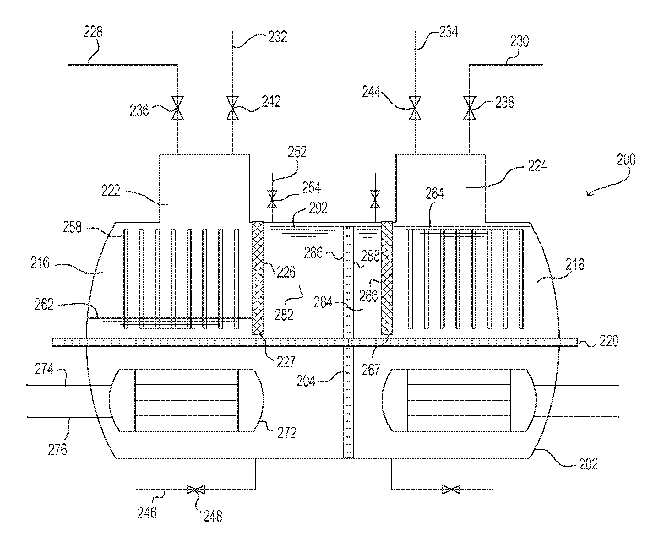
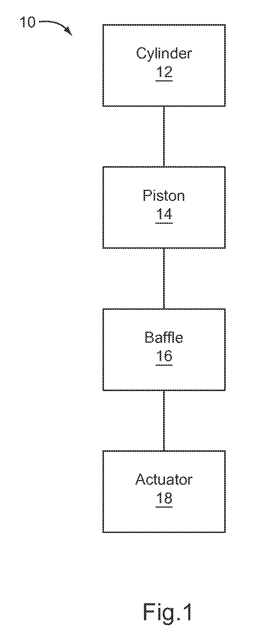
[0013]Devices and systems used to compress and / or expand a gas, such as air, and / or to pressurize and / or pump a liquid, such as water, are described herein. Pneumatic devices described herein can be used to compress gas within a cylinder or pressure vessel. As described herein, a piston can be movably disposed within a cylinder or pressure vessel and actuated to compress air within the cylinder or pressure vessel. Pneumatic devices as described herein can include what is referred as “a baffle” (also referred to herein as a “divider” or “separator”) disposed within the interior region of the cylinder. The baffle can provide a fluid-tight seal between the piston and the cylinder wall during movement of the piston relative to the cylinder. In some embodiments, pneumatic devices as described herein can be used in a compressed air energy storage (CAES) system.

[0014]In some CAES systems, devices can be actuated with, for example, hydraulic and / or pneumatic actuators. For example, in some ...


PUM


Abstract

An apparatus can include a pressure vessel that defines an interior region that can contain a liquid and / or a gas. A piston is movably disposed within the interior region of the pressure vessel. A divider is fixedly disposed within the interior region of the pressure vessel and divides the interior region into a first interior region on a first side of the divider and a second interior region on a second, opposite side of the divider. The piston is movable between a first position in which fluid having a first pressure is disposed within the first interior region and the first interior region has a volume less than a volume of the second interior region, and a second position in which fluid having a second pressure is disposed within the second interior region and the second interior region has a volume less than a volume of the first interior region.

Description

CROSS-REFERENCE TO RELATED APPLICATION [0001]This application claims priority to and the benefit of U.S. Provisional Patent Application Ser. No. 61 / 431,259, entitled “Compressor and / or Expander Device,” filed Jan. 10, 2011, the disclosure of which is hereby incorporated by reference herein in its entirety.BACKGROUND [0002]The invention relates generally to devices, systems and methods for the compression and / or expansion of a gas, such as air, and / or the pressurization of a liquid, such as water.[0003]Known devices and systems can include a cylindrical housing with a movable piston disposed therein. Some known devices include the use of a gas, such as air, to move the piston to produce an output of work. Some pneumatic devices are used to compress and / or expand a gas, such as air. For example, a piston can be moved within a cylinder to push or move the gas out of the cylinder at an increased pressure. Such a device can be used, for example, in a compressed air energy storage system....

Claims


Application Information

Patent Timeline
Patent Type & Authority Applications(United States)
IPC IPC(8): F02G1/053F01B29/10
CPCF02C6/16F02G1/02F04B23/021F04B23/023Y02E60/15F04B41/02Y02E60/16
Inventor INGERSOLL, ERIC D.ABORN, JUSTIN A.AALMANS, LUCBLEISKE, MATTHEW
Owner GENERAL COMPRESSION
Why Eureka
Try Eureka