
High resolution absolute orientation rotary magnetic encoder

a rotary magnetic encoder, absolute orientation technology, applied in the direction of instruments, measuring devices, using electrical means, etc., can solve the problems of inability to record the change in orientation, the foregoing process is tedious, and the angular resolution is limited

Active Publication Date: 2012-08-30
DEXTER MAGNETIC TECH
View PDF3 Cites 9 Cited by
  • Summary
  • Abstract
  • Description
  • Claims
  • Application Information

AI Technical Summary

Problems solved by technology

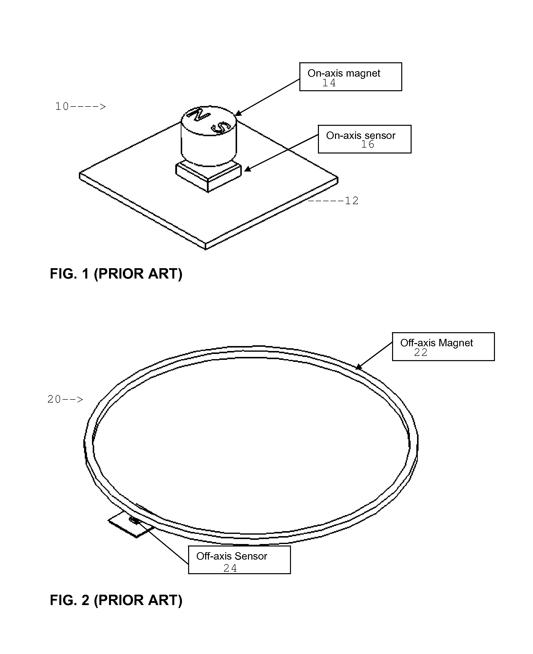
In an on-axis sensor, however, the angular resolution however is limited by signal levels within the sensor 16 and the ability of associated signal processing circuitry to covert small voltages induced in the sensing elements to orientation information with sufficient accuracy.
The foregoing process is tedious.
Further, in case the magnet ring rotational orientation changes during a subsequent power loss or power off condition, the change in orientation may not be recorded.
Therefore, upon power up, orientation detected by the sensor 24 may be in error, necessitating another homing operation.

Method used


Image

  • High resolution absolute orientation rotary magnetic encoder
  • High resolution absolute orientation rotary magnetic encoder
  • High resolution absolute orientation rotary magnetic encoder

Examples


example 1

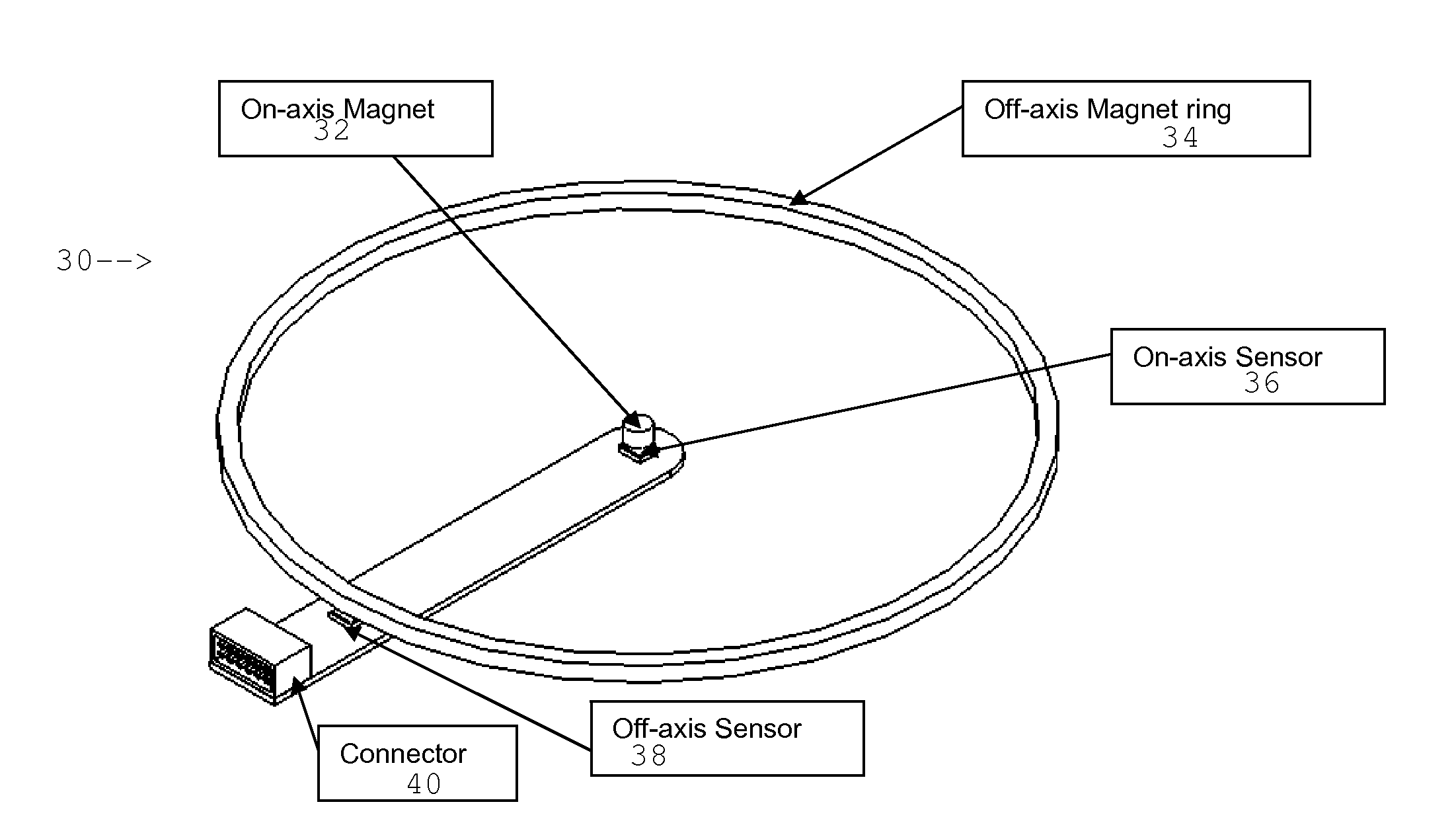
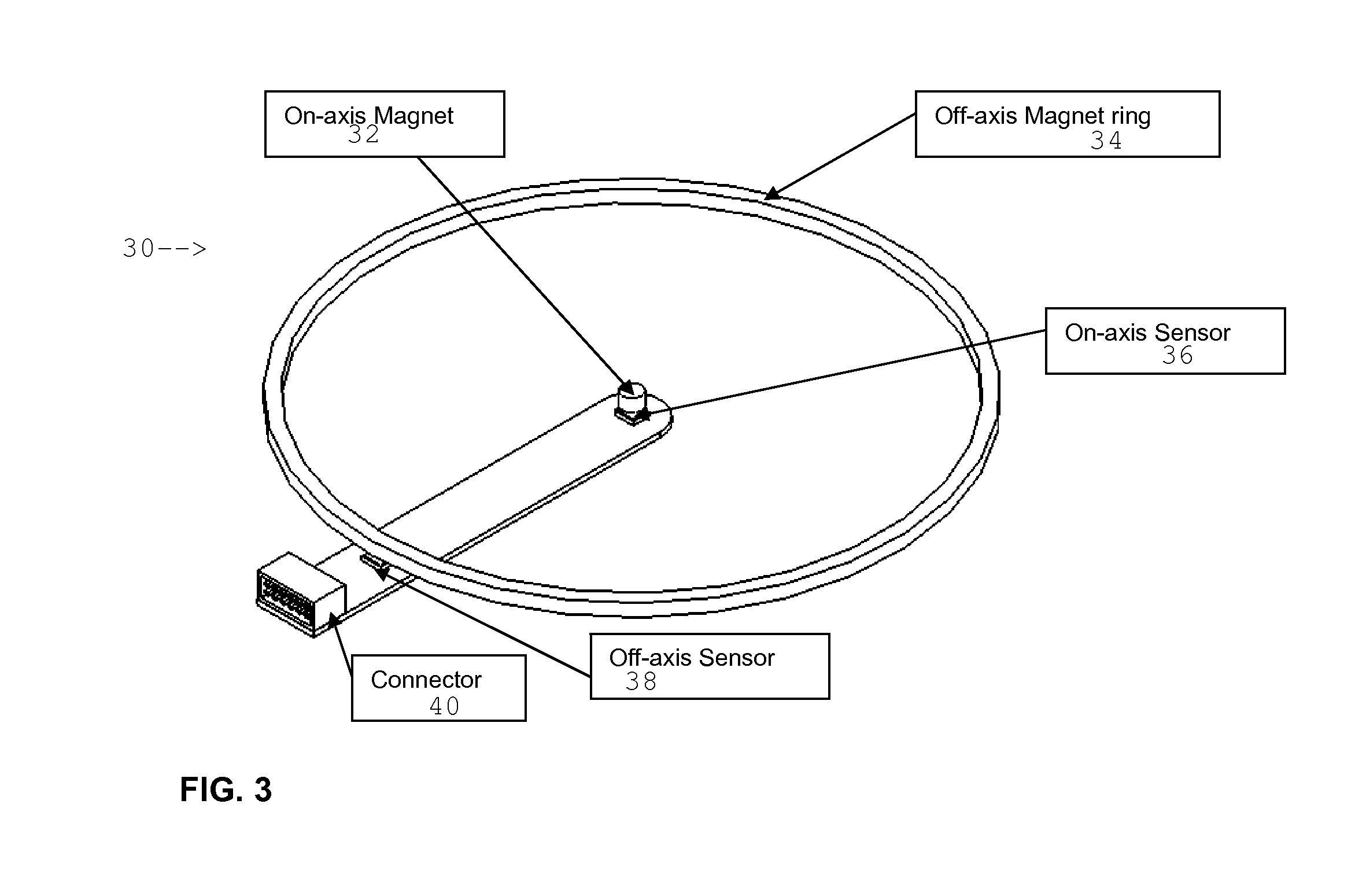
[0023]An encoder providing absolute position information with 18 bits of resolution combines an 6 bit resolution on-axis sensor (64 steps per revolution) with a 64 magnet pole pair magnet ring and an off-axis sensor with twelve bit resolution (4096 steps per pole pair). In the foregoing combination, the on-axis sensor provides absolute angular position information with 360 / 64=5.625° resolution. Because the magnet ring has 64 pole pairs, each pole pair precisely covers 5.625°. The off-axis sensor then provides absolute position information within each pole pair to a resolution 5.625 / 4096=0.001373291 degrees. This is equal to 360 / 218 degrees and may be represented as 18 bits of resolution.

[0024]A high accuracy absolute encoder with 18 bit resolution as described in this example can be implemented using off-the-shelf sensors such as AS5145 for on-axis sensing and AS5311 for off-axis sensing, both from Austriamicrosystems, and off-the-shelf magnets such as p / n 2910041, a 0.236″ diameter...

example 2

[0025]An encoder providing absolute position information with 24 bits resolution combines a 12 bit resolution on-axis absolute sensor (4096 steps / revolution) with a 4096 pole pair magnet ring and a 12 bit resolution off-axis sensor. Following similar calculation as in Example 1, the present example encoder can provide absolute rotation position to 24 bits of resolution, i.e. 0.0000214 degree.

[0026]Understanding the resolution numbers: The foregoing resolution numbers are small and their significance can be better understood by considering them in view of certain physical parameters.

[0027]First, consider the resolution in terms of sensor voltage output pulses (counts) per degree of encoder rotation. A 20 bit resolution encoder provides 2094 encoder counts per degree of rotation, i.e., one degree divided 2094 times. A 24 bit resolution encoder provides 46728 counts per degree using the same form of calculation.

[0028]By comparison, consider an 8 bit resolution encoder over a full encod...


PUM


Abstract

A rotary encoder includes a magnet disposed on a rotational axis of the encoder. The magnet is polarized transversely to the rotational axis. A first magnetic sensor is disposed on the rotational axis proximate the on-axis magnet. A magnet ring is disposed rotationally coaxially with the rotational axis and has a selected diametric distance from the axis. The magnet ring has a plurality of alternatingly polarized magnets. A number of pole pairs in the magnet ring is selected to match an angular resolution of the first magnetic sensor. A second magnetic sensor is disposed proximate the magnet ring.

Description

CROSS-REFERENCE TO RELATED APPLICATIONS[0001]Priority is claimed from U.S. Provisional Application No. 61 / 446,100 filed on Feb. 24, 2011. The foregoing application is incorporated herein by reference in its entirety.STATEMENT REGARDING FEDERALLY SPONSORED RESEARCH OR DEVELOPMENT[0002]Not applicable.BACKGROUND OF THE INVENTION[0003]1. Field of the Invention[0004]The invention relates generally to the field of rotary orientation encoders. More specifically, the invention relates to rotary encoders having high angular resolution and absolute orientation determination capability.[0005]2. Background Art[0006]Rotary encoders provide information about the angular position of rotating device with respect to a selected reference. One type of such encoder uses one or more magnets rotatably mounted with respect to a magnetic field sensor. When the magnet is mounted to a shaft, for example, the sensor provides a signal related to the rotation angle of the shaft with respect to the sensor. There...

Claims


Application Information

Patent Timeline
IPC IPC(8): G01B7/30
CPCG01D5/2454G01B7/30
Inventor PARAKKA, ANTHONY
Owner DEXTER MAGNETIC TECH
Learn More