
Solar Power Generation Apparatus Capable of Tracking Sunlight

Active Publication Date: 2012-08-30
FTC SOLAR INC
View PDF5 Cites 38 Cited by
  • Summary
  • Abstract
  • Description
  • Claims
  • Application Information

AI Technical Summary

Benefits of technology

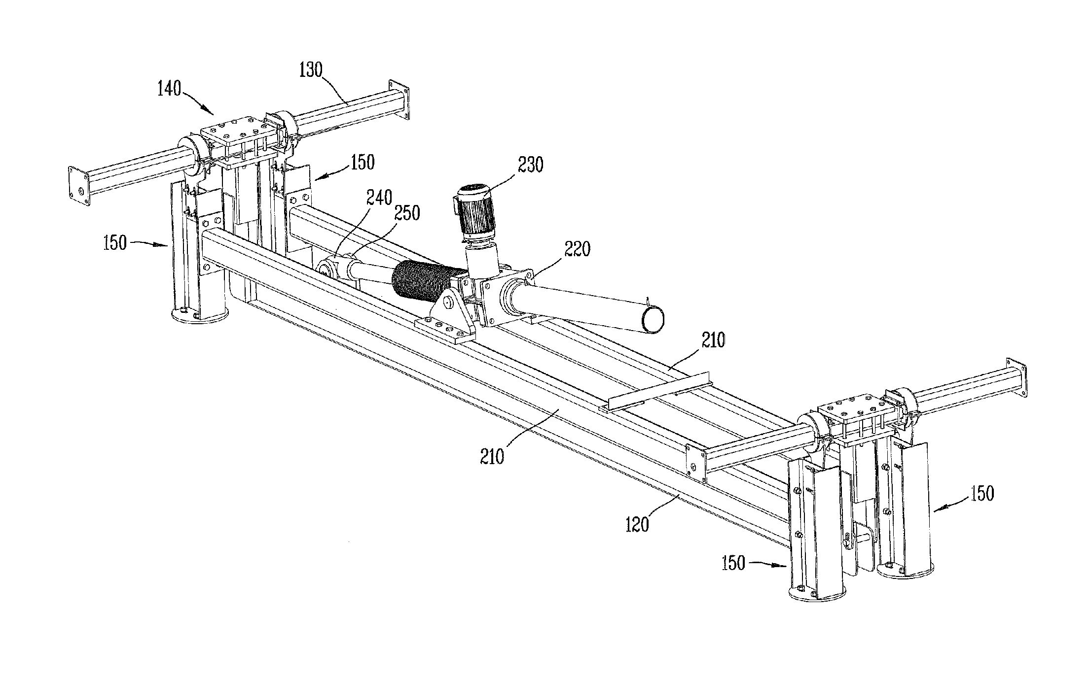
[0023]According to the invention having said structure, a minimum number of actuators can be used to operate multiple solar panels with simple power transmission structure, so that not only the installation cost can be reduced but the power consumption can be reduced so that the efficiency of power generation can be increased indirectly.
[0024]In addition, the actuator can be installed overlapped longitudinally; the installation area can be minimized.
[0025]Additionally, by connecting each part using the provided slot type bolt anchoring holes, as the tolerance due to such a non-uniform area can be effectively absorbed, the installation can be easily accomplished.BRIEF DESCRIPTION OF THE FIGURES
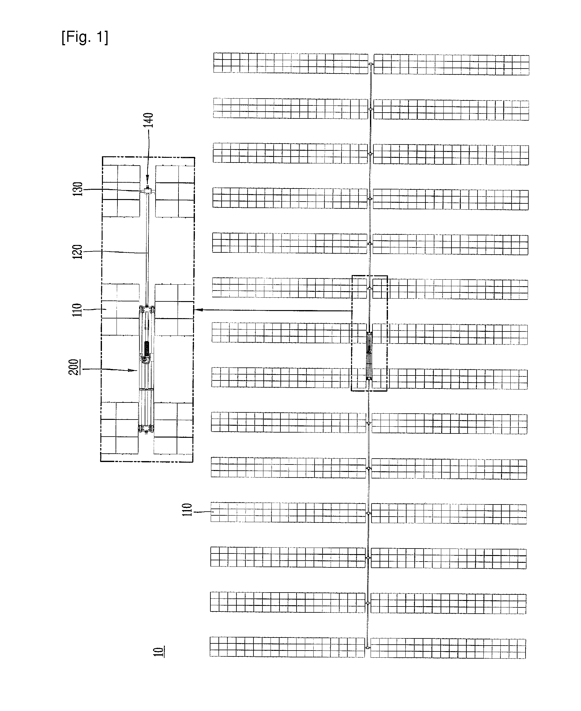
[0026]FIG. 1 illustrates a planar view of schematic array of the solar energy generation apparatus according to the present invention.
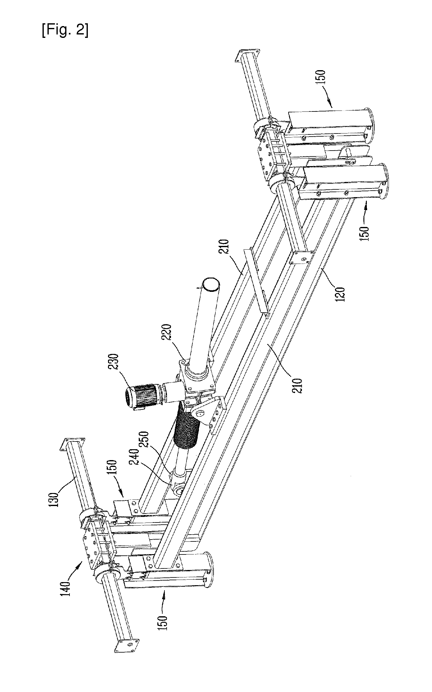
[0027]FIG. 2 illustrates the magnified perspective view of the drive unit.
[0028]FIG. 3 illustrates the magnified perspective view lever arm portion in FIG. 2.

Problems solved by technology

On the other hand, in terms of a power generation system using solar energy, a large number of solar panels are generally installed on a vast area of flat land and as it is impossible to install more than 2 panels of solar panels to overlap, a vast space of land is required.
Because of this, the power transmission structure to deliver a power generated from an actuator to each solar panel is complex and the power loss during the transmission is increased as well.
In addition, if you consider the cost of installation, a large number of solar panels must be installed in the limited land space but since separate space for an actuator is necessary, the usage of the space becomes low.
In addition, said torque tube is a type that extends to one direction, as deformation during the installation and transportation stage can be possible, it is not easy to correctly couple with said post.
As the solar power generation apparatus is generally installed outside area which is not flat, it is very difficult to install each component as it is designed.

Method used


Image

  • Solar Power Generation Apparatus Capable of Tracking Sunlight
  • Solar Power Generation Apparatus Capable of Tracking Sunlight
  • Solar Power Generation Apparatus Capable of Tracking Sunlight

Examples


Embodiment Construction

Technical Challenges

[0007]The present invention is devised to overcome the above mentioned traditional disadvantages, and to provide a solar power generation apparatus which uses a single actuator to rotate multiple solar panels effectively.

[0008]In addition, the present invention is devised to provide a solar power generation apparatus which does not require separate space for an actuator.

[0009]In addition, the present invention is devised to provide a solar power generation apparatus which effectively absorbs the tolerance due to the changes and the non-uniform soils.

Technical Solution

[0010]In order to achieve said technical challenges, the present invention provides a solar power generation apparatus, which is comprised of: torque tubes which are arranged to form a plurality of columns; a plurality of solar panels which are installed along each torque tube; posts which support each torque tube to be rotatable; lever arms which are coupled with each torque tube; a linkage which is...


PUM


Abstract

The present invention relates to a solar power generation apparatus, which comprises: torque tubes which are arranged to form a plurality of columns; a plurality of solar panels which are installed along each torque tube; posts which rotatably support each torque tube; lever arms which are coupled with each torque tube; a linkage which is disposed on the lower side of the torque tubes and is connected to each lever arm; an actuator which reciprocates the linkage in the longitudinal direction of the linkage, thereby rotating the torque tubes around an axis based on the longitudinal direction of the torque tubes; and a bed frame which is installed between some of the plurality of posts, wherein the actuator is supported thereon.

Description

FIELD OF INVENTION[0001]The present invention is related to a solar power generation apparatus. More particularly, the present invention is related to a solar power generation apparatus having a tracking device to rotate the angle of the solar panel in relation to the angle of the sun.BACKGROUND ART[0002]In order to achieve said technical challenges, the present invention is a synthetic resin bearing for a photovoltaic tracking system including the first and second bearing members coupled with each other for forming a bearing assembly, wherein each of the first and second bearing members comprises of a pair of side plate members facing each other; a friction member positioned between the outer peripheral portions of the pair of side plates and having an arc shaped section; and a reinforcement member for connecting the pair of side plates and the friction member, and the first and second bearing members have a coupling protrusion and a concave portion for receiving the coupling protr...

Claims


Application Information

Patent Timeline
IPC IPC(8): H01L31/052F24S50/20
CPCF24J2/5264F24J2/541Y02E10/47F24J2002/5493F24J2002/5468H01L31/04F24S25/70F24S30/425F24S2030/136F24S2030/18Y02E10/50H02S20/32H01L31/042
Inventor JANG, YUN-KYU
Owner FTC SOLAR INC
Learn More