
Lamp tube structure and assembly thereof

a technology of lamp tube and assembly, which is applied in the direction of lighting and heating apparatus, semiconductor devices for light sources, and support devices for lighting and heating devices. it can solve the problems of complicated assembly process, low driving voltage, and led consumption of less power than traditional fluorescent lamp tubes

Inactive Publication Date: 2012-08-23
LEXTAR ELECTRONICS CORP
View PDF16 Cites 94 Cited by
  • Summary
  • Abstract
  • Description
  • Claims
  • Application Information

AI Technical Summary

Problems solved by technology

Since LED has lower driving voltage and long life-span, LED consumes lower power than traditional fluorescent lamp tube.
However, a problem of LED tube arises when assembling the LED tube.
Generally, the LED tube has two end caps, and each of the end caps has two separable individual parts, which makes the assembling process more complicated and increases the cost for assembling.
In addition, the end cap with two parts is not strong enough for protecting electrical terminals from impact.
Consequently, the reliability of the LED tube is reduced.

Method used


Image

  • Lamp tube structure and assembly thereof
  • Lamp tube structure and assembly thereof
  • Lamp tube structure and assembly thereof

Examples


Embodiment Construction

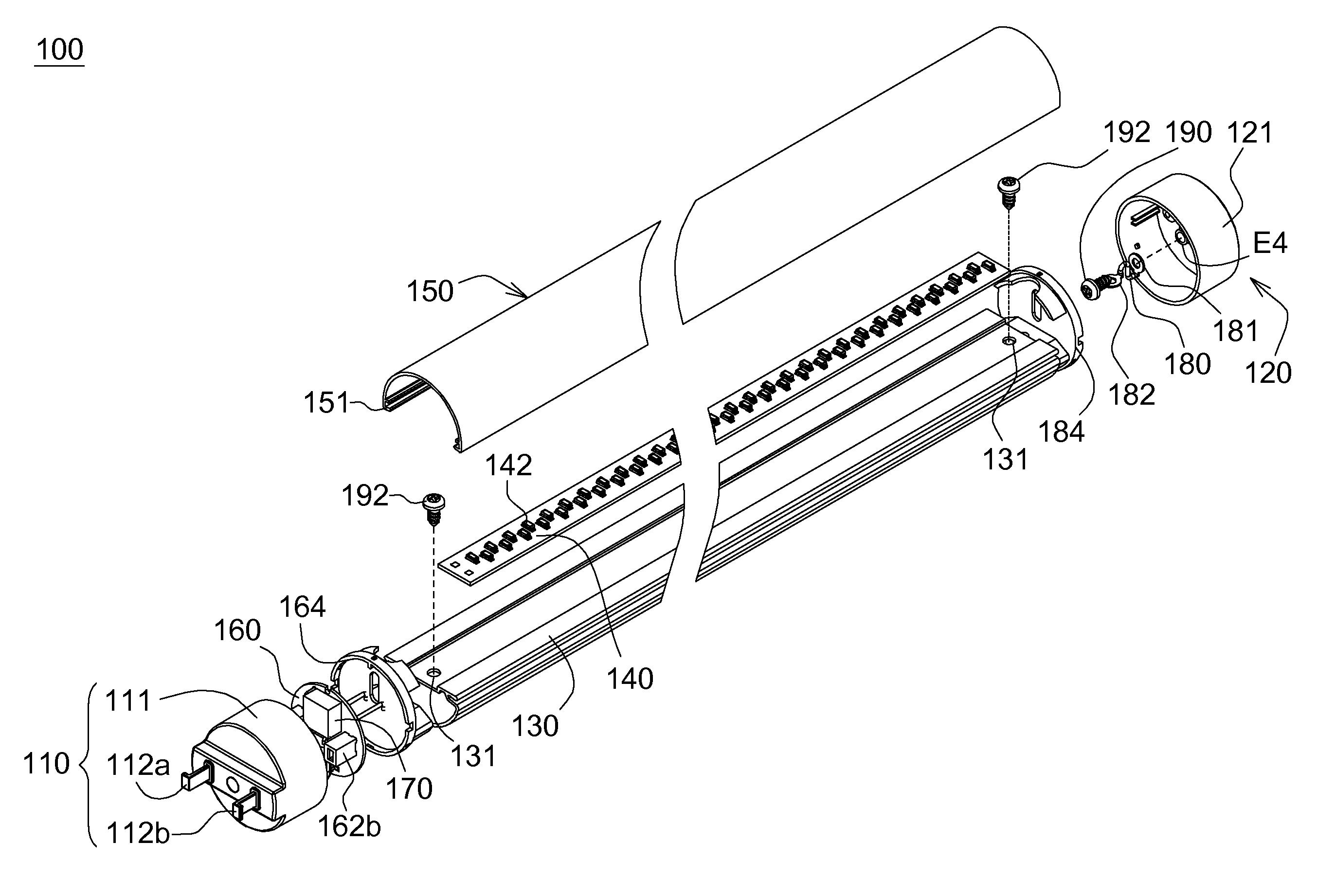
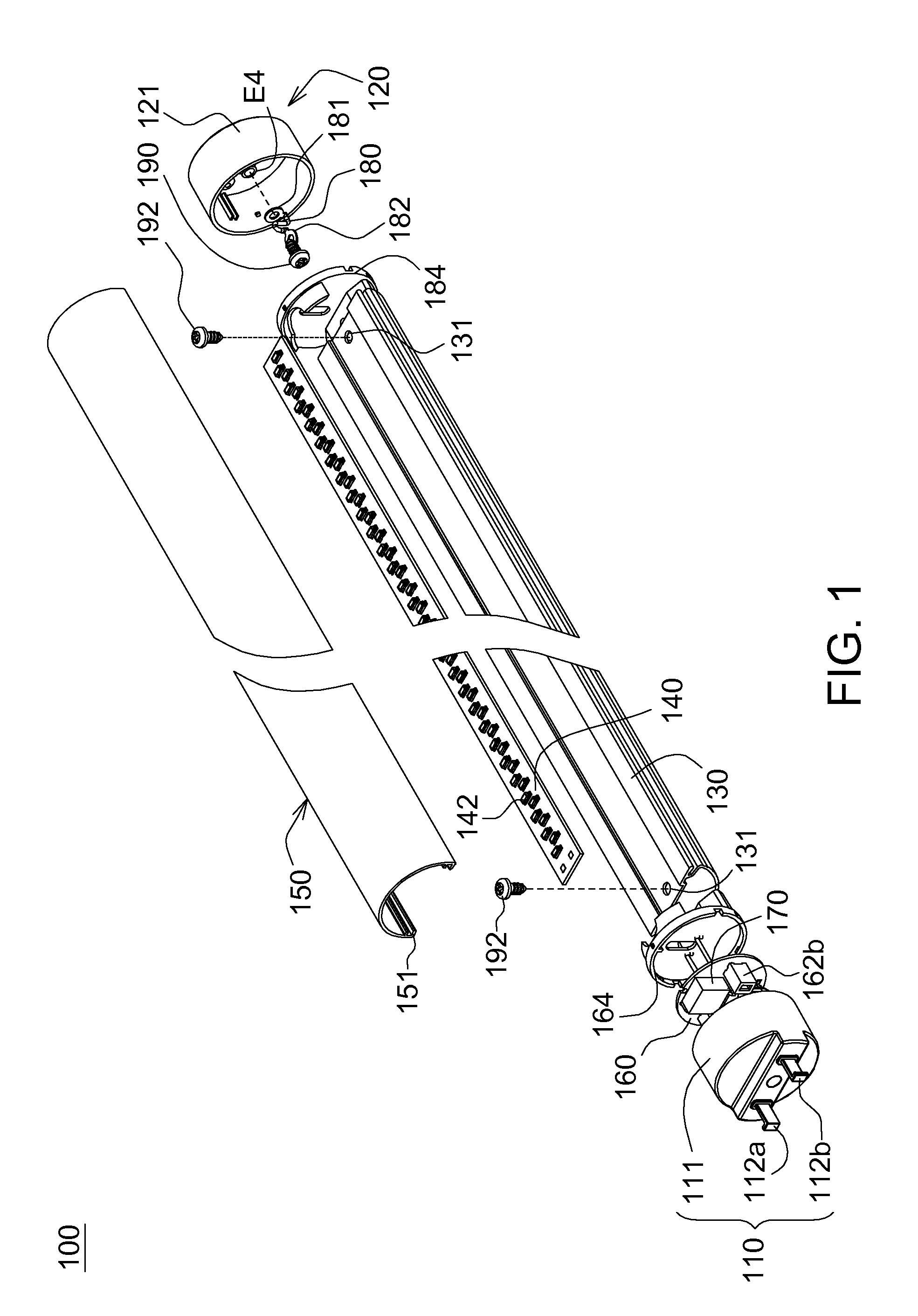
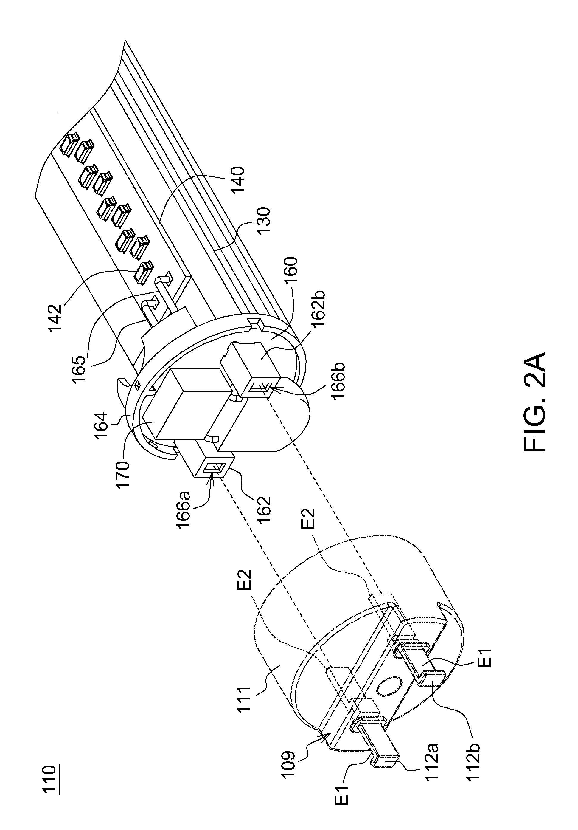
[0021]According to a lamp tube structure and assembly thereof disclosed in an embodiment of the disclosure, a first end cap of the lamp tube is provided with a pair of electrical terminals by insert molding to enhance the joint strength, and a second end cap of the lamp tube is provided with a grounding terminal by insert molding to enhance the joint strength. Consequently, even the impact occurs, the electrical terminals or the grounding terminal is well protected and the probability of being broken is reduced. In the present embodiment of the disclosure, the electrical terminals are supplied with input power, for example, Direct Current (DC) power, for driving the light emitting element array of the lamp tube, and the grounding terminal is installed to eliminate noise via a heat sink holder of the lamp tube to prevent the lamp tube from the interference of noise.

[0022]The lamp tube structure of the exemplary embodiment of the disclosure is exemplified by a GX16 lamp tube, but the ...


PUM


Abstract

A lamp tube structure includes a first end cap, a second end cap, a heat sink holder, a light emitting element array and a lamp cover. The first end cap includes a pair of electrical terminals and a first insulating portion. The electrical terminals are integrated into the first insulating portion by insert molding, and one end of each electrical terminal is protruded from an outside of the first insulating portion. The second end cap includes a grounding terminal and a second insulating portion. The grounding terminal is integrated into the second insulating portion by insert molding, and one end of the grounding terminal is protruded from an outside of the second insulating portion. The light emitting element array is disposed on top surface of the heat sink holder. A bottom surface of the lamp cover is fixed on the heat sink holder for receiving the light emitting element array.

Description

[0001]This application claims the benefit of U.S. provisional application Ser. No. 61 / 444,848, filed Feb. 21, 2011, the subject matter of which is incorporated herein by reference.BACKGROUND[0002]1. Technical Field[0003]The disclosure relates in general to a lamp tube structure, and more particularly to a lamp tube structure and assembly thereof.[0004]2. Description of the Related Art[0005]In the modern society, light emitting diodes (LED) are so popular and convenient. There are many applications for LED such as backlight modules, headlamps, and indicator lamps. Since LED has lower driving voltage and long life-span, LED consumes lower power than traditional fluorescent lamp tube. Thus, conventional fluorescent lamp tubes are gradually replaced by LED tubes.[0006]However, a problem of LED tube arises when assembling the LED tube. Generally, the LED tube has two end caps, and each of the end caps has two separable individual parts, which makes the assembling process more complicated...

Claims


Application Information

Patent Timeline
IPC IPC(8): F21V29/00F21V21/00F21V25/00
CPCF21K9/175F21V23/002F21V29/74F21Y2103/003H05B33/0803F21Y2101/02F21Y2103/10F21Y2115/10F21K9/272H05B45/00H05B47/20
Inventor LAI, CHUN-MINGLIN, CHIH-YEN
Owner LEXTAR ELECTRONICS CORP
Learn More