Eureka AIR delivers breakthrough ideas for toughest innovation challenges, trusted by R&D personnel around the world.

Liquid circulation system and ink-jet printer

a circulation system and liquid circulation technology, applied in printing and other directions, can solve the problems of uneven amount of drop liquid or clogged drop discharge, complicated configuration, and inability to appropriately diffuse fine particles in the ink flowing rou

Active Publication Date: 2012-08-09
MIMAKI ENG
View PDF2 Cites 35 Cited by
  • Summary
  • Abstract
  • Description
  • Claims
  • Application Information

AI Technical Summary

Benefits of technology

[0015]According to the present invention, it becomes possible to control liquid stagnation in a flowing route, and enable appropriate circulation of the liquid.

Problems solved by technology

Unfortunately, the technology described in Patent Document 1 and Patent Document 2 requires that the pump should additionally be installed in the circulation channel connecting the ink tank and the ink-jet head so that the configuration becomes complicated.
Moreover, since the circulation of the ink does not reach the ink-jet head, the fine particles in the ink flowing route cannot appropriately be diffused.
Such high-viscosity liquid causes an uneven amount of drop liquid or clogged discharge of drop liquid due to flowing route resistance.
Therefore, unfortunately it takes some time to shift into actual operating condition (in which the temperature and circulation of the liquid become homogeneous) after starting operation of the industrial-use liquid coating machine.

Method used


Image

  • Liquid circulation system and ink-jet printer
  • Liquid circulation system and ink-jet printer
  • Liquid circulation system and ink-jet printer

Examples


Embodiment Construction

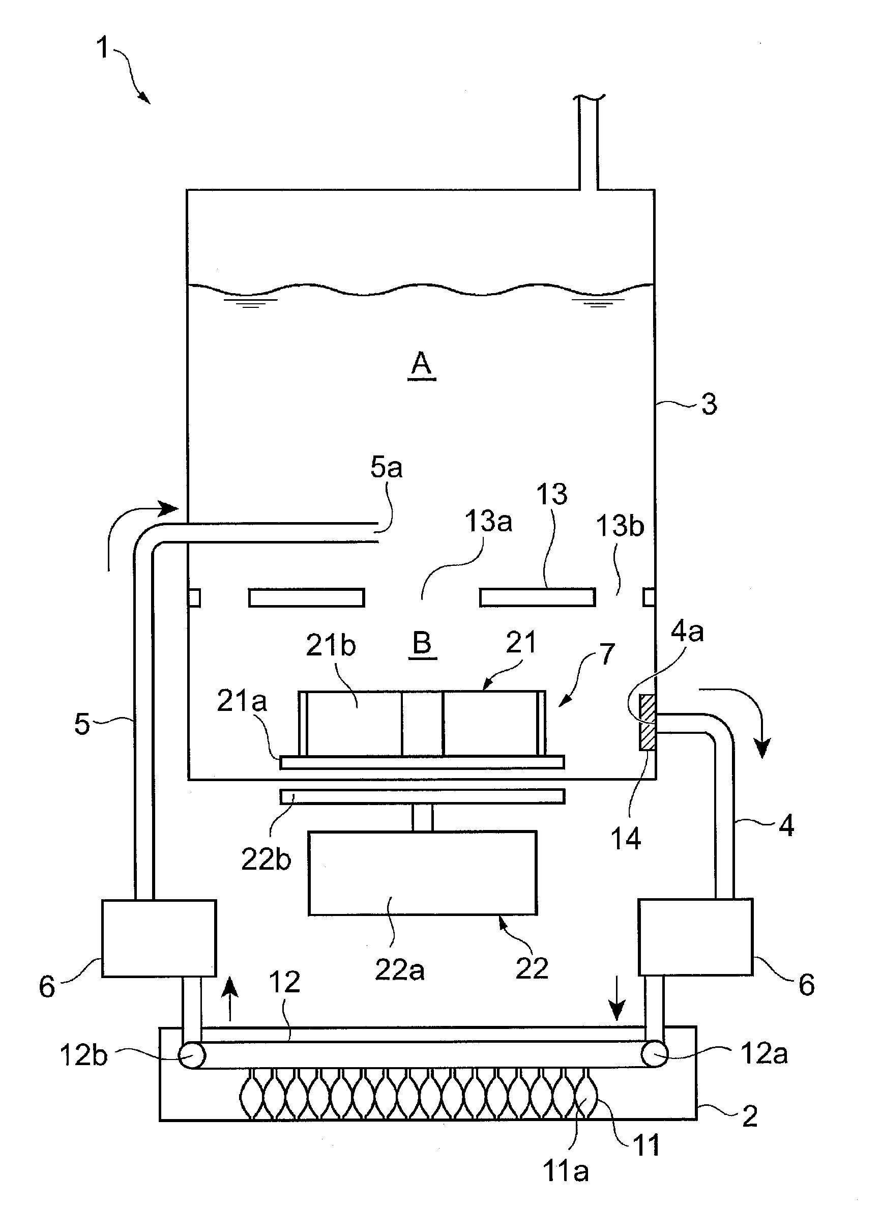
[0023]A preferred embodiment of a liquid circulation system according to the present invention is described below in detail with reference to the accompanying drawings. In the present embodiment, the liquid circulation system according to the present invention is applied to an ink circulation system mounted in an ink-jet printer that is a liquid discharging machine. In the explanation below, the same or equivalent portion is provided with the same reference numeral.

[0024]The ink circulation system according to the present embodiment is mounted in the ink-jet printer, and it circulates ink through an ink flowing route of the ink-jet printer. As the ink to be circulated in the ink circulation system, used is metallic ink, pearl ink, white ink, and so on that contains fine particles of pigment and the like in a solvent.

[0025]FIG. 1 is a perspective view of the ink circulation system according to the embodiment, and FIG. 2 is a perspective drawing of an ink tank shown in FIG. 1, meanwhi...


PUM


Abstract

An ink circulation system includes: an ink-jet head in which a shared ink flowing route is formed, an ink tank, a supply flowing route for supplying ink from the ink tank to the shared ink flowing route, a reflux flowing rout for refluxing the ink from the shared ink flowing route to the ink tank, and a differential pressure generating unit for generating a differential pressure in the ink tank. The differential pressure generating unit is equipped with an impeller placed inside the ink tank, and a drive unit placed outside the ink tank. Then, the drive unit operates to turn the impeller, by means of remote driving, for generating a differential pressure between a supply port of the supply flowing route and a reflux port of the reflux flowing route so as to circulate the ink through the ink flowing route.

Description

FIELD OF THE INVENTION [0001]The present invention relates to a liquid circulation system to be mounted in a liquid discharging machine such as an ink-jet printer, from which liquid is discharged, and an ink-jet printer.BACKGROUND [0002]Conventionally, known as a liquid discharging machine discharging liquid are an ink-jet printer that discharges ink, an industrial-use liquid coating machine that discharges high-viscosity liquid such as edible oil, adhesive, and so on, and the like. Such a liquid discharging machine includes a liquid discharging head for discharging liquid and a liquid container that supplies the liquid to the liquid discharging head. Then, while the liquid being supplied from the liquid container to the liquid discharging head, the liquid is discharged from the liquid discharging head.[0003]In the meantime, used in an ink-jet printer is ink containing fine particles of pigment and the like, such as metallic ink, pearl ink, white ink, and so on. Having a great speci...

Claims


Application Information

Patent Timeline
IPC IPC(8): B41J2/18
CPCB41J2/175B41J2/1752B41J2/18B41J2/17556B41J2/17596B41J2/17553
Inventor IGAWA, TOMOMIYOKOYAMA, SEIICHI
Owner MIMAKI ENG
Why Eureka
Eureka Blog
Learn More