
Travel simulator arrangement

Inactive Publication Date: 2012-08-09
IPGATE
View PDF15 Cites 9 Cited by
  • Summary
  • Abstract
  • Description
  • Claims
  • Application Information

AI Technical Summary

Benefits of technology

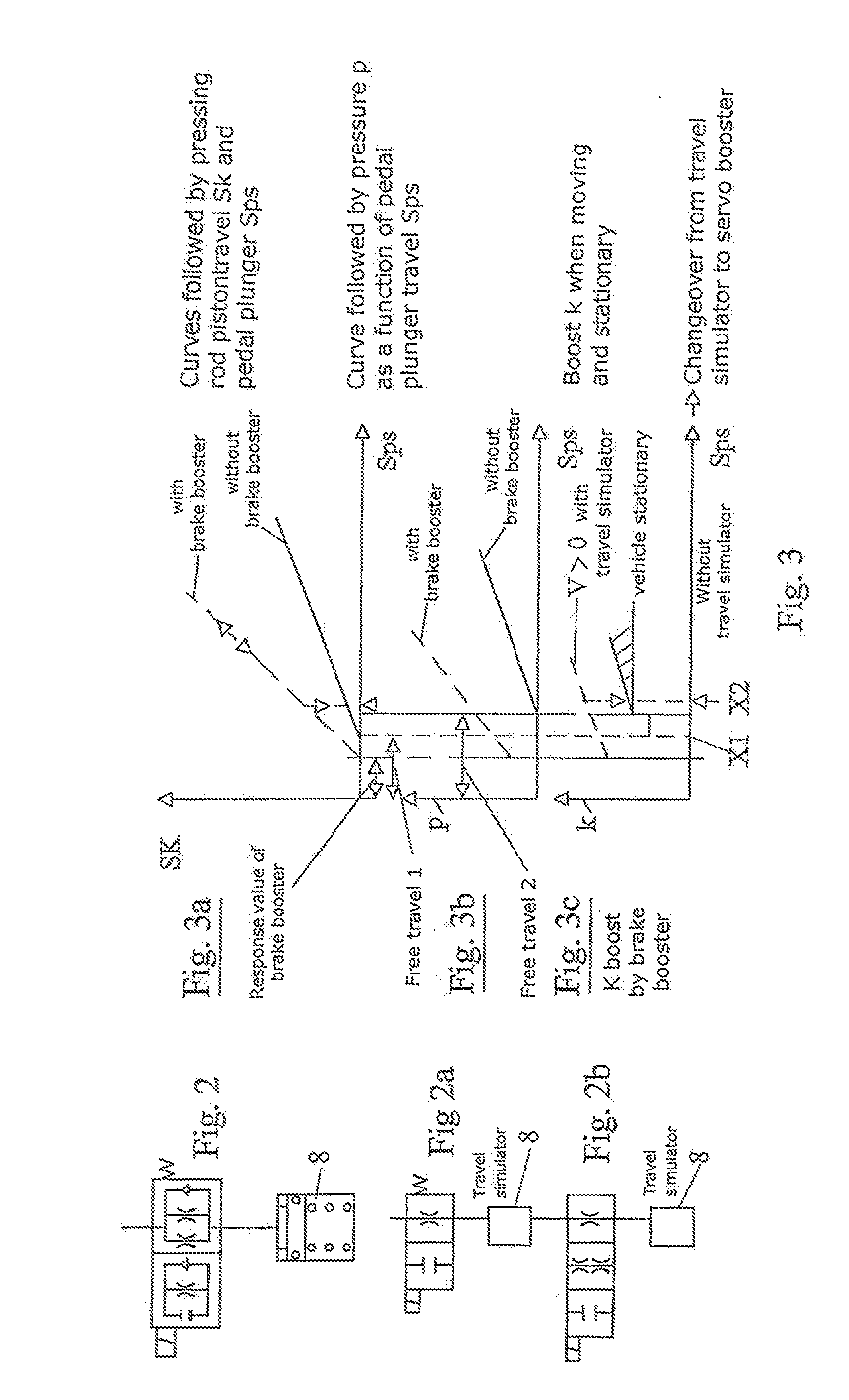
[0048]The schematic diagram, shown in the figure, of a choke with a return valve is derived from FIG. 2. As an alternative to the choke shown in FIG. 2, the throttling effect can also be realised by a temperature-dependent throttling element which is connected in particular at inlet E to the auxiliary piston 6 and at outlet A to the magnetic valve 18.
[0049]FIG. 5 shows a throttling element 44 with orifice plates 45 w

Problems solved by technology

A remedy can thus be provided for the effect which is a nuisance when stationary, which arises from the travel simulator coming up against the stop, and/or for the effects which irritate the driver in the event of faults, when for example there is no feedbac

Method used


Image

  • Travel simulator arrangement
  • Travel simulator arrangement
  • Travel simulator arrangement

Examples


Example

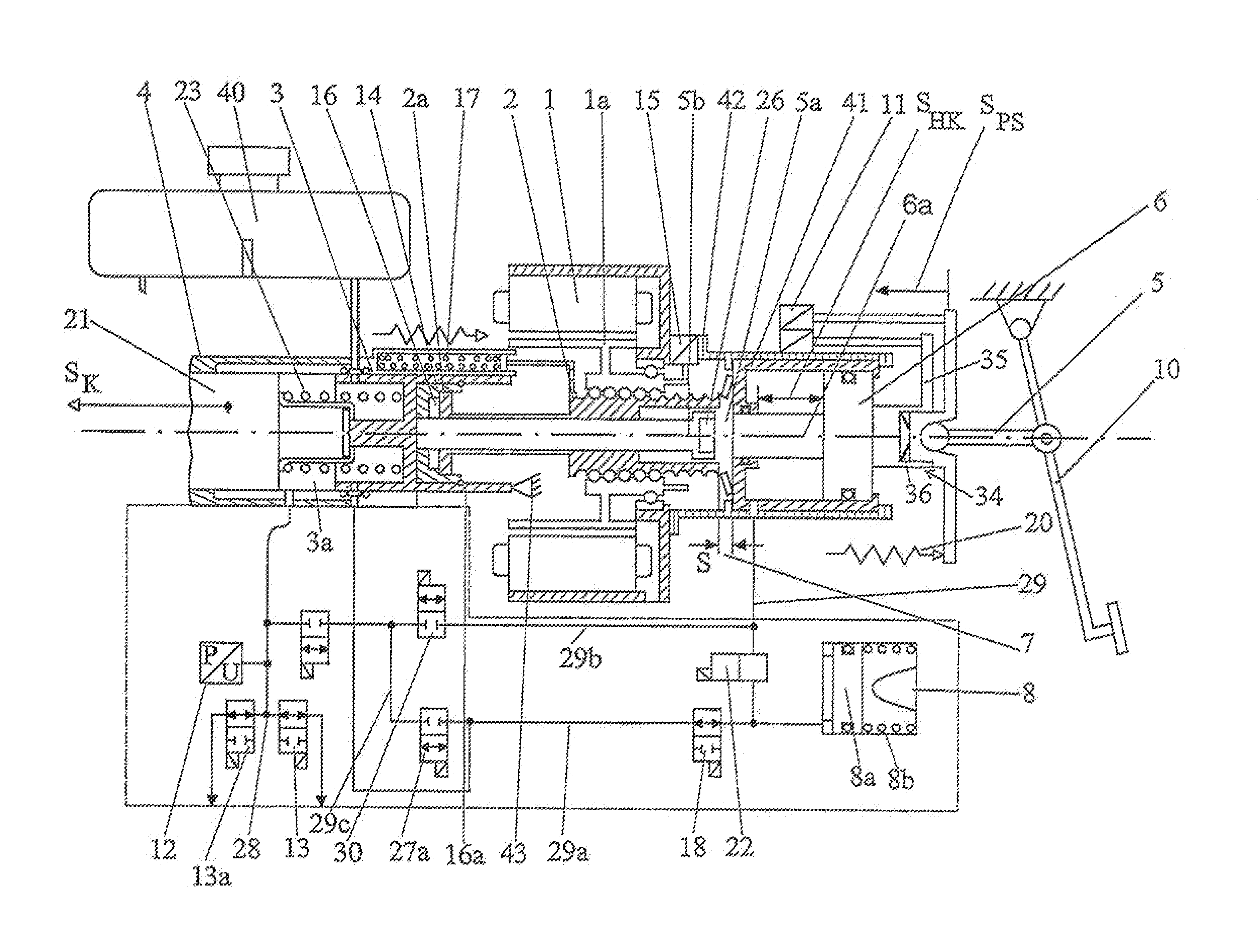
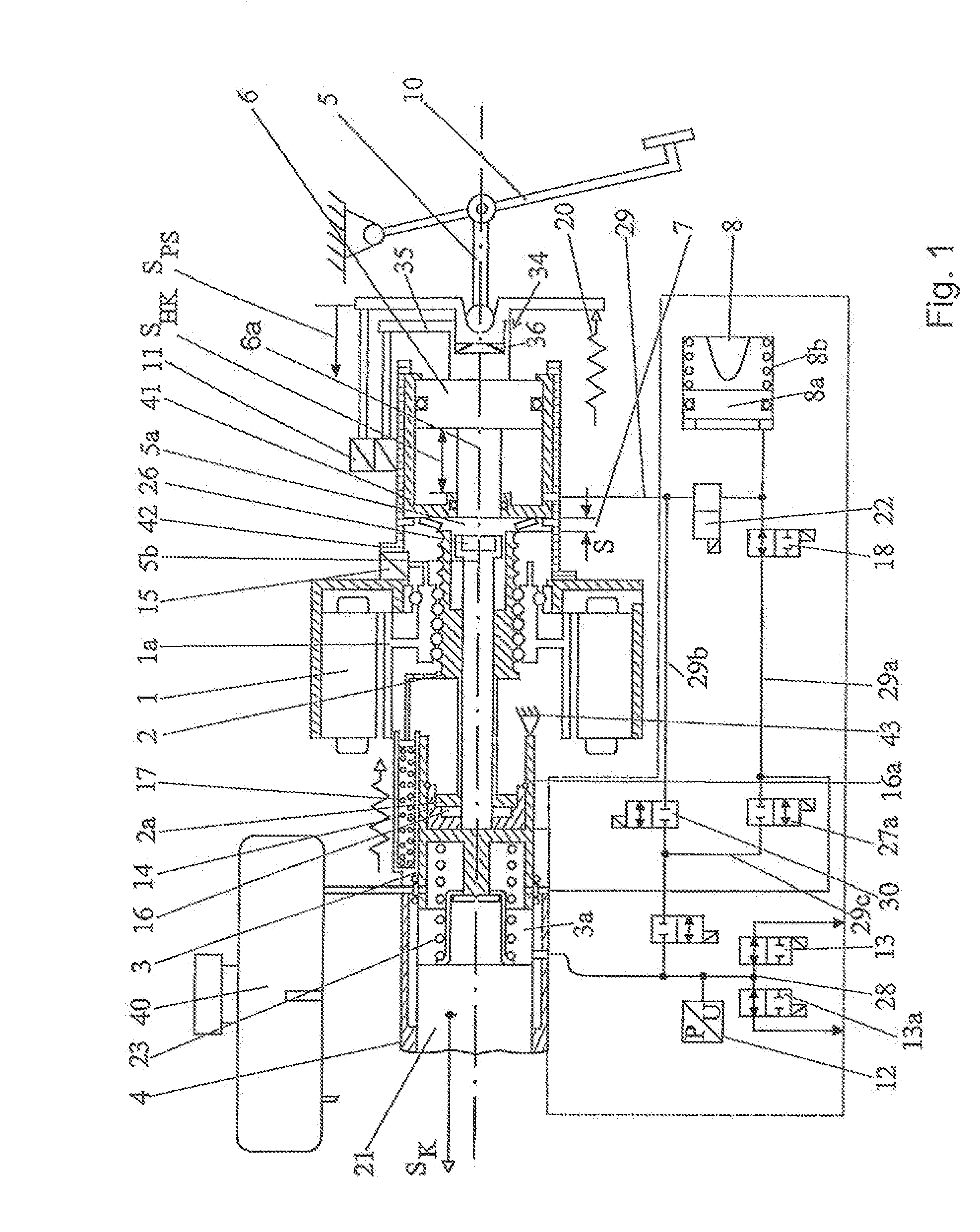
[0023]The embodiment of actuating system for a vehicle brake which is shown in FIG. 1 has a first piston-and-cylinder unit 4 in whose body a first piston (pressing-rod piston) 3 and a second piston (floating piston) 21 are arranged to be axially displaceable. By means of springs, the pistons 3, 21 are supported against the end-wall of the cylinder (not shown) and against one another 23. The first piston 3 takes the form of a hollow piston. The piston-and-cylinder unit 4 is connected to a boosting arrangement which has a rotary drive in electric motor which acts in both directions, which is controlled by an electronic control unit (ECU) (not shown) and which has a stator 1 and rotor 1a and a transmission mechanism for converting a rotary movement into a linear movement and for gearing the ratio of drive. The rotor 1a is mounted in the housing of the drive by means of two bearings. The transmission mechanism is provided with a recirculating-ball spindle 2 which is arranged concentrica...


PUM


Abstract

The invention relates to a travel simulator arrangement, in particular for motor vehicle braking systems, having a travel simulator which has a means, in particular a resilient or elastic one, to represent an actuating travel as a function of an actuating force, characterised in that the travel simulator (8) has assigned to it an adaptive means which produces a variable opposing force to the travel simulator force.

Description

[0001]The invention relates to a travel simulator arrangement, in particular for vehicle braking systems.PRIOR ART[0002]In new developments in new braking systems, a clear trend is apparent towards integration, i.e. towards all components being combined into a single unit structure, and towards the use of pedal travel simulators, which have various advantages. Disadvantages of what are referred to as brake boosters using a pedal travel simulator are a synthetic feel to the pedal at high pedal speeds. In conventional servo boosters, for example as vacuum-operated brake boosters, the force on the pedal is boosted by a booster member. There is always a direct feedback of force in this case at the time of any pedal movement. In the case of travel simulators it is the travel simulator spring which acts and in the case of hydraulic travel simulators it is a fixed throttle.[0003]The stop to which the travel simulator spring is subject, which is situated at approximately 40% of the total pe...

Claims


Application Information

Patent Timeline
IPC IPC(8): B60T7/04G05G1/30
CPCB60T7/042B60T8/4077Y10T74/2054B60T13/662B60T8/409
Inventor LEIBER, HEINZKOGLSPERGER, CHRISTIANHECKER, CARSTENWINZER, RAINER
Owner IPGATE
Learn More