Desiccating container
a desiccating container and container technology, applied in the field of containers, can solve the problems of poor usability efficiency and many defects in the current desiccating container, and achieve the effects of reducing the containing space in the insert, increasing the utility efficiency of the desiccant, and increasing the gap siz
- Summary
- Abstract
- Description
- Claims
- Application Information
AI Technical Summary
Benefits of technology
Problems solved by technology
Method used
Image
Examples
first embodiment
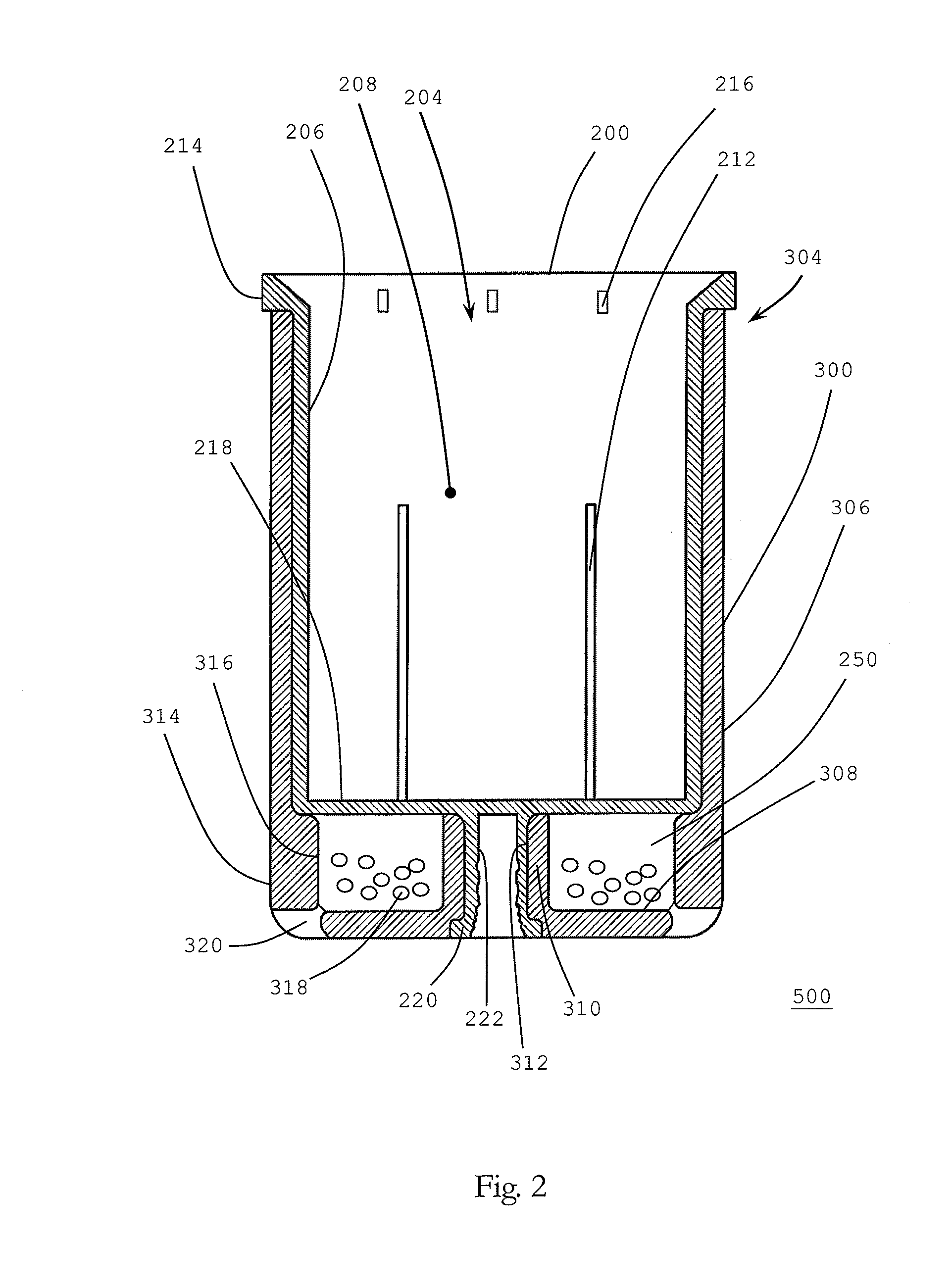
[0025]Please refer to FIG. 2, which is the schematic diagram illustrating a first embodiment for the insert and the desiccant element in accordance with the present invention. The insert 200 in FIG. 2 is a first cylindrical tank 206 having containing space 208 therein and the opening 204 at one end thereof. The bulk in the first cylindrical tank 206 is the containing space 208 that the insert 200 has. A primary storing space for the desiccating container consists of the containing space 208 and is utilized for reserving, for example, test strips, pills, capsules, drugs or moist-proof requiring articles. There are a plurality of body apertures 212 opened on the body of the first cylindrical tank 206. The insert has a boundary outwardly protruded for forming a lip-like edge 214 at the opening 204. There are also a plurality of edge apertures 216 opened on the lip-like edge 214. The insert 200 has a first bottom 218 having an outer surface, a surface toward a direction opposite to the ...
third embodiment
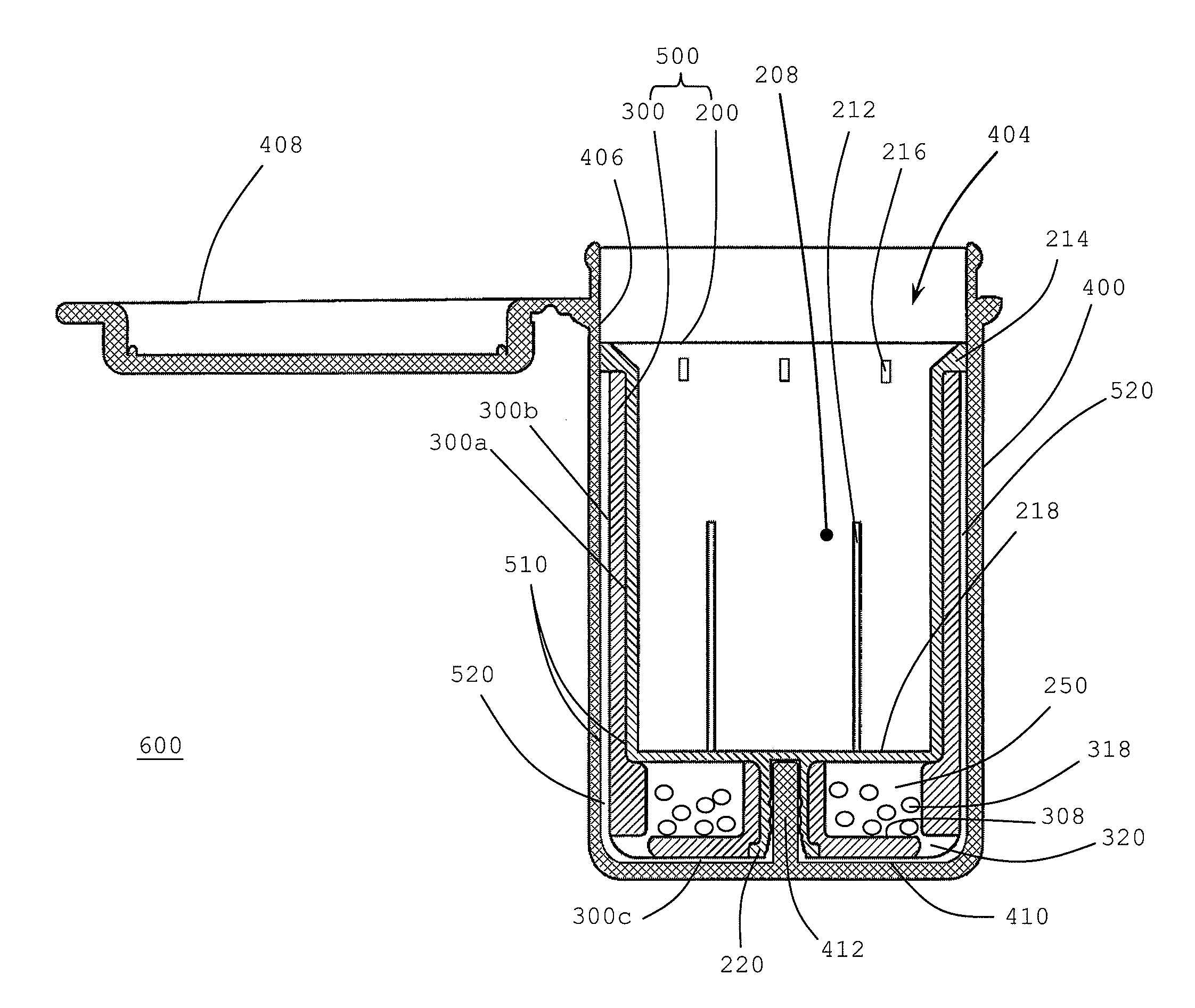
[0038]Since the moisture, humidity or wet in the containing space 208 flows between the inner gap 580 and the outer gap 590, the desiccant element 300, in particular the outer surface 300b and the bottom surface 300c thereof, can absorb the moisture, humidity or wet in the containing space 208 through the path defined by outer gap 590 and the edge apertures 216, and to the inner surface 300a, can absorb the moisture, humidity or wet in the containing space 208 through the path defined by the inner gap 580 and the body apertures 212. The moisture-absorbing material 318 in the reserved space 250 can absorb the moisture, humidity or wet in the containing space 208 through the path defined by the bottom apertures 320 and the outer gap 590. In such third embodiment, the inner surface 310a of the desiccant element 300 can be fully utilized to absorb moisture, humidity or wet, due to the configuration of the inner gap 580.
[0039]In brief, since the desiccant element 300 divides the gap 510 ...
fourth embodiment
[0042]The moisture, humidity or wet in the containing space 208 can be directly absorbed by the inner surface 300a of the desiccant element 300 or flows to the inner gap 580 through the aperture 650 on the desiccant element 300 to be absorbed by the outer surface 300b and the bottom surface 300c of the desiccant element 300. The moisture-absorbing material 318 in the reserved space 250 can absorb the moisture, humidity or wet in the containing space 208 through the bottom apertures 320 and the outer gap 590. In such fourth embodiment, the multiple sides of the desiccant element 300 including the inner surface 300a, outer surface 300b and the bottom surface 300c can be fully utilized to absorb moisture, humidity or wet.
[0043]Furthermore, there are still several paths formed in the third embodiment as follows including a first path, through which a moisture, humidity or wet in the containing space freely flows, defined by the containing space 208, and the respective edge apertures 216...
PUM
 Abstract
Description
Claims
Application Information
 - R&D
- Intellectual Property
- Life Sciences
- Materials
- Tech Scout
- Unparalleled Data Quality
- Higher Quality Content
- 60% Fewer Hallucinations
Browse by: Latest US Patents, China's latest patents, Technical Efficacy Thesaurus, Application Domain, Technology Topic, Popular Technical Reports.
© 2025 PatSnap. All rights reserved.Legal|Privacy policy|Modern Slavery Act Transparency Statement|Sitemap|About US| Contact US: help@patsnap.com


