
Method for determining stratigraphic position of a wellbore during driling using color scale interpretation of strata and its application to wellbore construction operations

a technology of color scale and stratigraphic position, applied in the field of drilling wellbores, can solve the problems of limited vertical resolution of seismic data obtained by reflection seismic techniques at the earth's surface (or in a body of water in marine seismic surveying) and the need for modification of predetermined wellbore trajectories

Inactive Publication Date: 2012-07-26
APACHE CORPORATION
View PDF1 Cites 45 Cited by
  • Summary
  • Abstract
  • Description
  • Claims
  • Application Information

AI Technical Summary

Problems solved by technology

It is known in the art that such techniques as the foregoing have limited resolution.
For example, seismic data obtained by reflection seismic techniques at the earth's surface (or in a body of water in marine seismic surveying) may be limited in vertical resolution.
Such limitations frequently result in predetermined wellbore trajectories requiring modification during drilling in order to maintain the well trajectory within a selected formation or set of formations.
The foregoing methodology has been proved to be effective in many cases, but is subject to certain limitations.
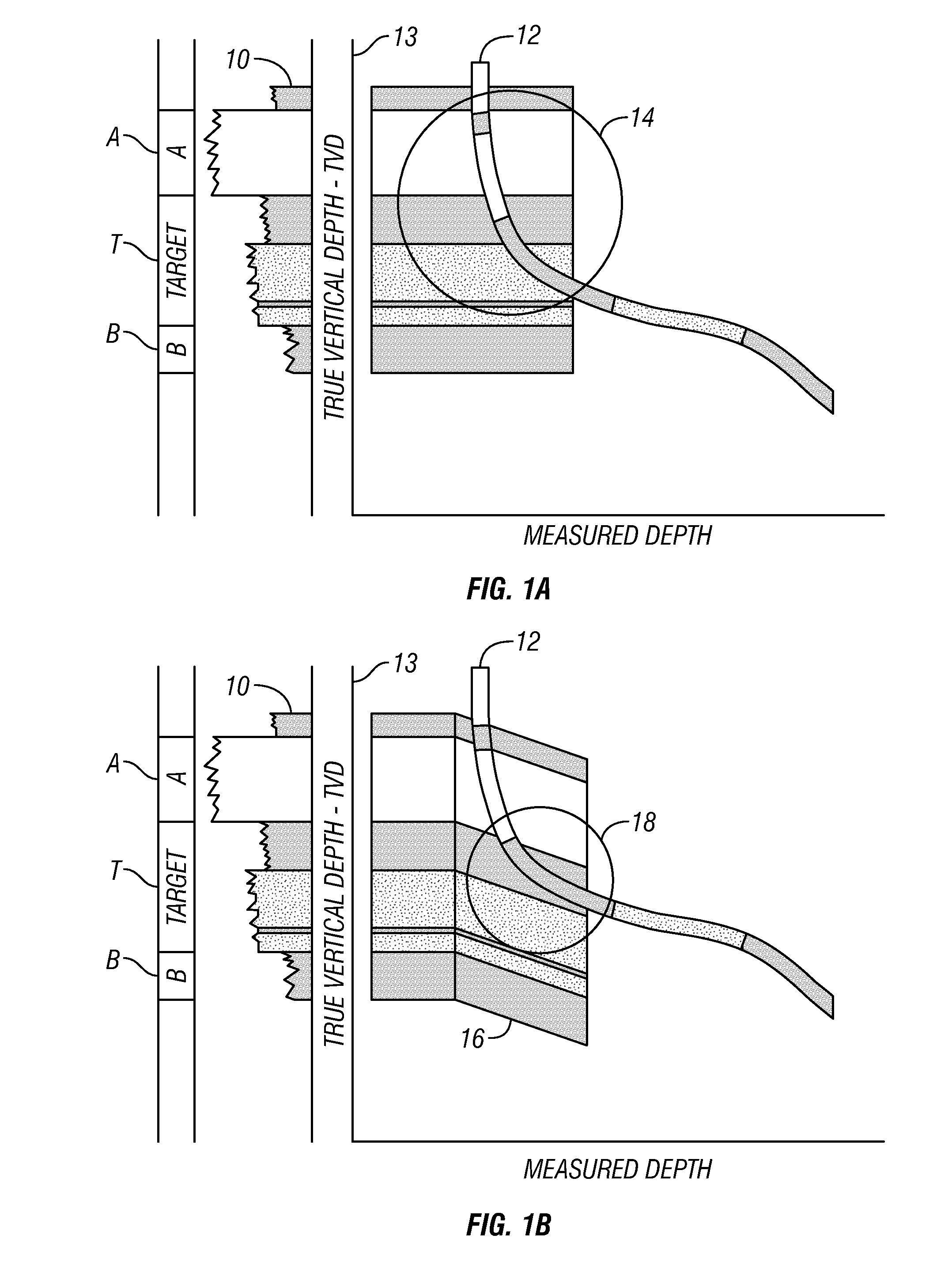
One of the limitations is that the correlation is made in only one dimension (TVD or TST) and therefore could sometimes be very difficult, possibly leading to an incorrect structural interpretation.
Incorrect structural interpretation may result in the well trajectory being placed outside the desired formations.
Such placement may result in reduced wellbore productivity or increased production of undesirable materials (e.g., water) from a particular wellbore.

Method used


Image

  • Method for determining stratigraphic position of a wellbore during driling using color scale interpretation of strata and its application to wellbore construction operations
  • Method for determining stratigraphic position of a wellbore during driling using color scale interpretation of strata and its application to wellbore construction operations
  • Method for determining stratigraphic position of a wellbore during driling using color scale interpretation of strata and its application to wellbore construction operations

Examples


Embodiment Construction

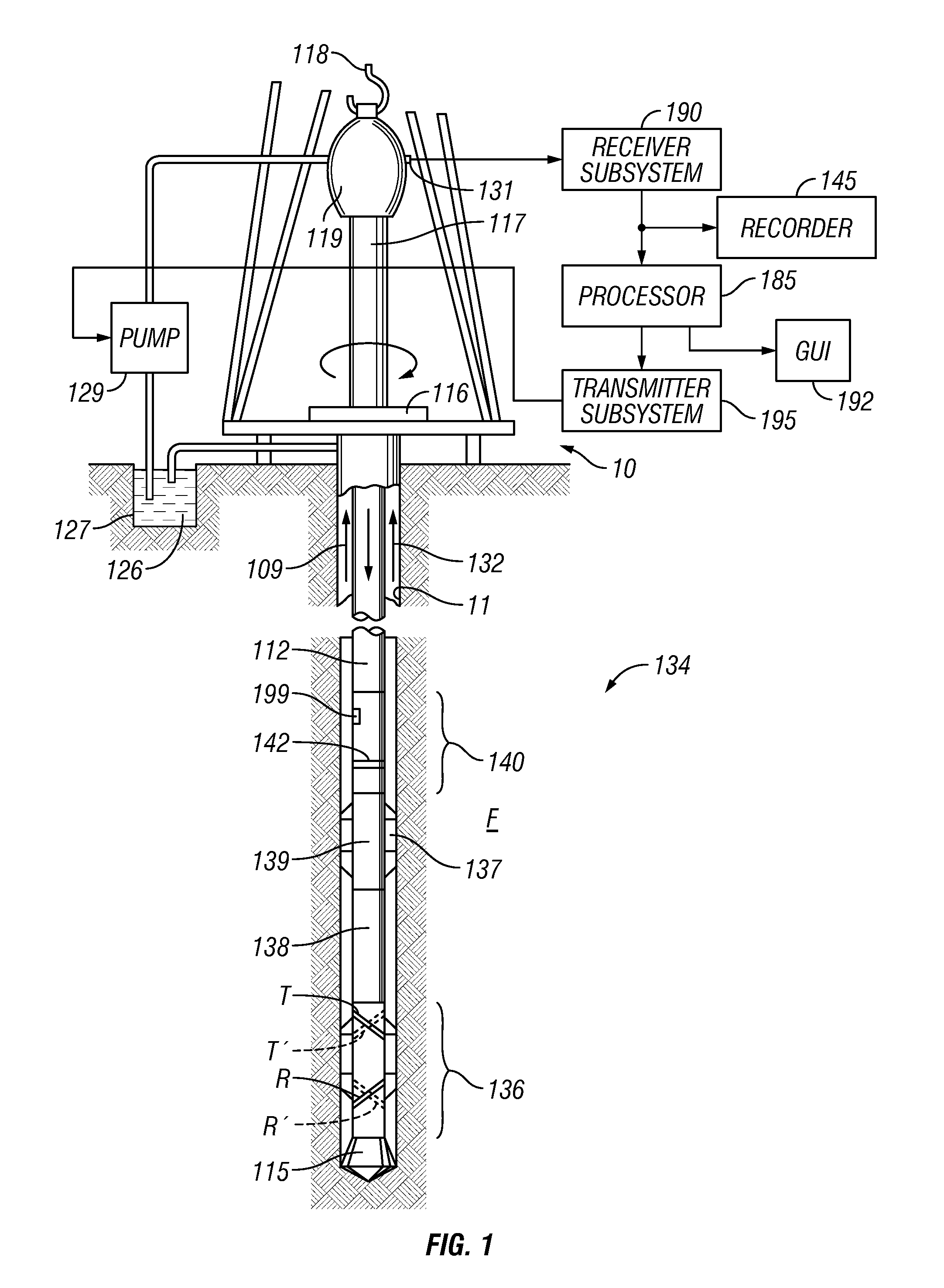
[0021]FIG. 1 illustrates a drilling rig and a drill string in which an instrument for making measurements during wellbore drilling may be used in methods according to the present invention can be used. A land-based platform and derrick assembly 110 are shown positioned over a wellbore 111 penetrating subsurface rock formations F. In the illustrated example, the wellbore 111 is formed by rotary drilling in a manner that is well known in the art. Those of ordinary skill in the art given the benefit of this disclosure will appreciate, however, that the present invention finds application in directional drilling applications, for example, using rotary steerable directional drilling systems or “steerable” hydraulic motors. Further, the invention is not limited to land-based drilling but is equally applicable to marine based wellbore drilling.

[0022]A drill string 112 is suspended within the wellbore 111 and includes a drill bit 115 at its lower end. The drill string 112 may be rotated by ...


PUM


Abstract

A method for formation structural interpretation while drilling a wellbore through subsurface rock formations includes interpreting rock formation strata with respect to measurements of a formation physical property made with respect to depth in an offset wellbore. A color is assigned to each of a plurality of selected value ranges of the measurements. The physical property of the formation is measured while drilling the wellbore through the subsurface rock formations. A color is assigned to the measurements made while drilling based on the assigned color to each of the selected value ranges. The assigned colors made while drilling are used to estimate a stratigraphic position of the wellbore during the drilling by comparing the assigned colors made while drilling to the colors assigned from the offset wellbore.

Description

CROSS-REFERENCE TO RELATED APPLICATIONS[0001]Priority is claimed from U.S. Provisional Application No. 61 / 498,643 filed on Jun. 20, 2011 and U.S. Provisional Application No. 61 / 436,246 filed on Jan. 26, 2011, both of which are incorporated herein by reference in their entirety.STATEMENT REGARDING FEDERALLY SPONSORED RESEARCH OR DEVELOPMENT[0002]Not applicable.BACKGROUND[0003]The invention relates generally to the field of drilling wellbores through subsurface rock formations. More specifically, the invention relates to methods for determining the stratigraphic position of a wellbore within layered strata for the purpose of placing a well trajectory within selected strata for a selected lateral distance within the strata, and the use of such trajectory determination in wellbore construction and / or completion operations.[0004]Wellbores are drilled through selected subsurface rock formations for, among other purposes, extraction of materials such as oil and gas from the formations. One...

Claims


Application Information

Patent Timeline
Patent Type & Authority Applications(United States)
IPC IPC(8): G06F19/00
CPCG01V1/345E21B47/022
Inventor CAYCEDO, FRANCISCO
Owner APACHE CORPORATION
Learn More