Steel rail clip assembly

a technology of steel rail and assembly, which is applied in the direction of track superstructure, construction, and transportation, etc., can solve the problems of reducing the practical value of the steel rail clip assembly in use, affecting the safety of people on the train, and unable to prevent loosening of the clip, so as to reduce the risk of related property loss and injury, and the effect of not being easily removed

Inactive Publication Date: 2012-07-26
WANG MING SHUN +1
View PDF1 Cites 4 Cited by
  • Summary
  • Abstract
  • Description
  • Claims
  • Application Information

AI Technical Summary

Benefits of technology

[0009]Therefore it is a primary object of the present invention to provide a steel rail clip assembly in which a clip is covered and located by the locating member so that the clip cannot be removed easily without special tools. The steel rail clip assembly can prevent falling of the clip of the steel rail caused by vibration of trains or malicious damage, knocking on railways so as to ensure the safety of train traffic services and reduce the risk of related property losses and injuries. The practical value of the steel rail clip assembly in use is increased.

Problems solved by technology

The train can only move along rail tracks smoothly.
However, there is no design that prevents loosening of the clip.
Thus during movement of trains, the displacement or even falling of the clip resulted from vibration occurs frequently and this could jeopardize the safety of people on the train.
The clip may be disassembled and sold or damaged and destroyed by malicious people.
The safety of the train is also affected.
Although the above way by using bolts or pins to fix the outer end of the insertion rod of the clip can reduce falling or disassembling of the clip, there are certain problems in use.
Bad people can still disassemble the clips by simple tools so that the train may leave the tracks and get damaged that are jeopardizing the safety of passengers.

Method used


Image

  • Steel rail clip assembly
  • Steel rail clip assembly
  • Steel rail clip assembly

Examples


Embodiment Construction

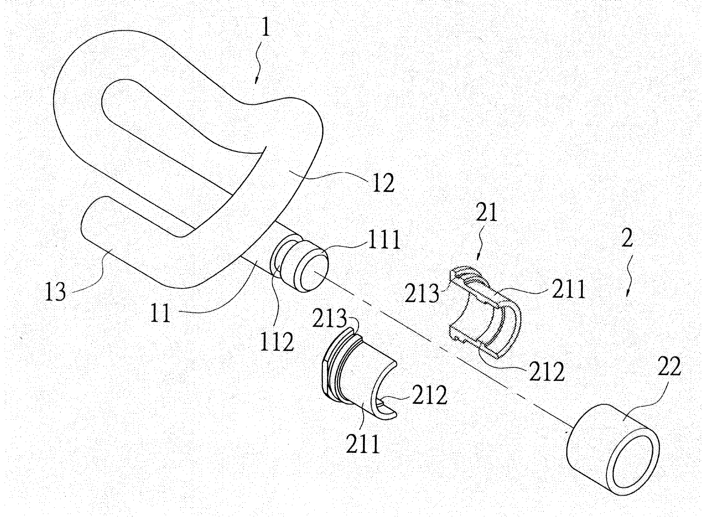
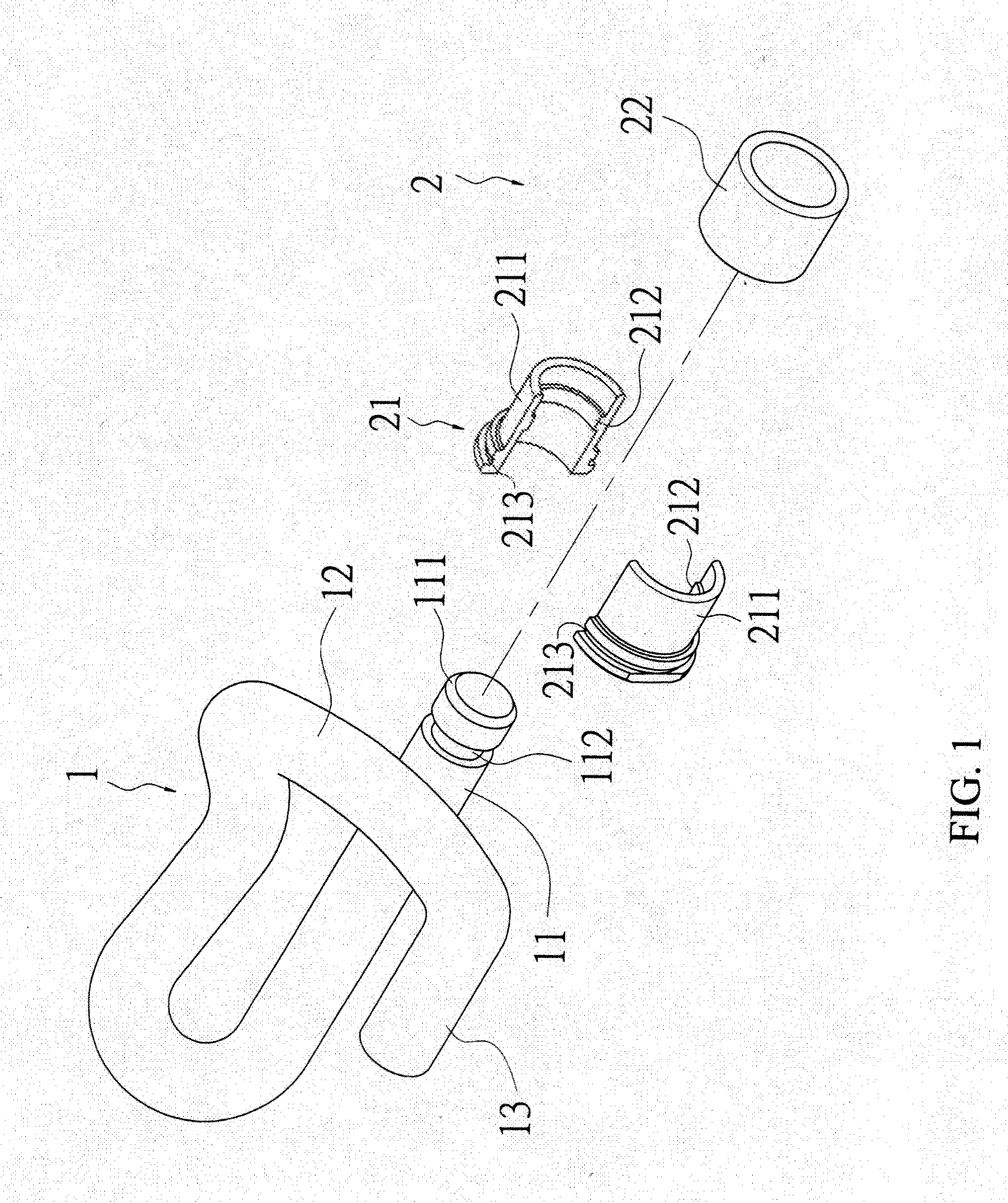
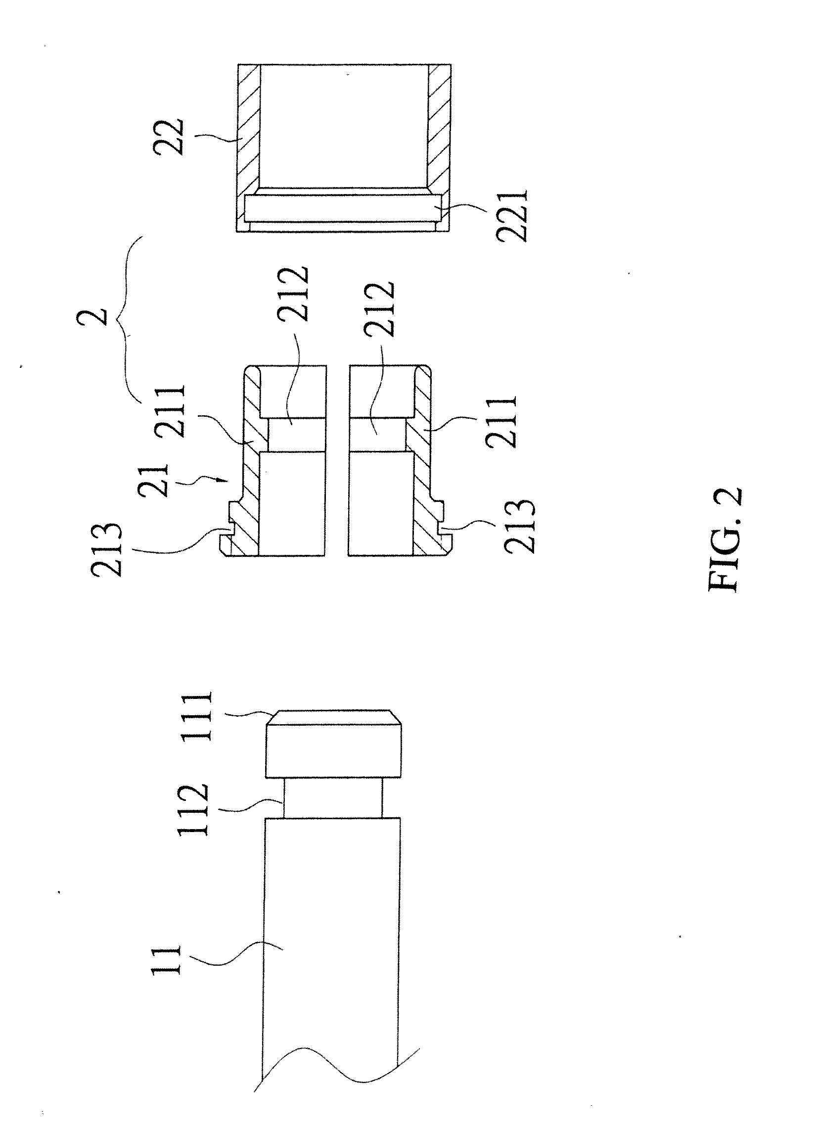
[0020]Refer to FIG. 1 and FIG. 2, an explosive view and a partial, enlarged, cross sectional view of an embodiment according to the present invention are revealed. An embodiment of a steel rail clip assembly mainly includes a clip 1 and a locating member 2.

[0021]With reference of FIG. 3, the clip 1 that looks like the letter “e” or “PR” viewed from a certain angle is formed by a bent metal bar. The clip 1 consists of at least one straight insertion rod 11, a cross part 12 bending from one side of the insertion rod 11 to the other side of the insertion rod 11, and a press part 13 connected with the cross part 12. The lowest portions of the clip 1 are positioned on two sides of the cross part 12. Moreover, no matter viewed from the top side or the bottom side, the cross part 12 crosses both sides of the insertion rod 11. A bevel 111 is formed on an outer end of the insertion rod 11 and a locating slot 112 is mounted concavely on an outer edge of the insertion rod 11.

[0022]The locating...


PUM


Abstract

A steel rail clip assembly having a clip and a locating member is revealed. A locating slot is arranged at an outer edge of an insertion rod of the clip while the locating member includes an inner bushing and an outer bushing mounted to each other. The inner bushing includes a locating block arranged at an inner surface and corresponding to the locating slot of the insertion rod. A locking projecting part and a corresponding locking concave part are respectively disposed on the inner bushing and the outer bushing. Thereby the clip is located by the locating member and unable to be removed easily without special tools. The falling of the clip of the steel rail caused by vibration of trains or malicious damage, knocking on railways is avoided. Thus the safety of train traffic services is ensured and the risk of related property losses and injuries is reduced.

Description

BACKGROUND OF THE INVENTION[0001]1. Fields of the Invention[0002]The present invention relates to a steel rail clip assembly, especially to a steel rail clip assembly that avoids the falling of the clips caused by vibration of trains or malicious damage, knocking on railways so as to ensure the safety of train traffic services and reduce the risk of related property losses and injuries. Thus the practical value of the steel rail clip assembly is improved.[0003]2. Descriptions of Related Art[0004]Trains with features of high speed and large capacity are a common and popular tool for long distance transportation. The train can only move along rail tracks smoothly.[0005]The rail track made of steel is fixed on a cross tie by a clip. The shape of the clip is like the letter “e” while being viewed from a certain angle so as to be called the e-shaped clip. The clip is produced by bending of a metal bar and is composed of a straight insertion rod, a cross part that bends from one side of t...

Claims


Application Information

Patent Timeline
Patent Type & Authority Applications(United States)
IPC IPC(8): E01B9/02E01B29/24E01B13/00
CPCE01B9/483E01B9/303
Inventor WANG, MING-SHUNWANG, MING-HSIANG
Owner WANG MING SHUN
Why Eureka
Try Eureka