Rotating device and robot arm device

a technology of rotating device and rotating arm, which is applied in the direction of mechanical control device, process and machine control, instruments, etc., can solve the problems of difficult to secure a spatial area passing through the inside of the rotation axis, and difficult to allow cables and flexible pipes to pass through the inside of the fixed portion and the rotating portion

Inactive Publication Date: 2012-07-26
SEIKO EPSON CORP
View PDF5 Cites 4 Cited by
  • Summary
  • Abstract
  • Description
  • Claims
  • Application Information

AI Technical Summary

Benefits of technology

[0013]According to the configuration, when the rotating portion rotates with respect to the fixed portion, misalignment between surfaces on which the first ring-shaped magnetic body and the second ring-shaped magnetic body respectively rotate and a surface orthogonal to the rotation axis can be suppressed, therefore, the distance of the gap to be changed can be reduced. According to this, it is possible to suppress damage caused by contact between the first ring-shaped magnetic body and the second ring-shaped magnetic body as well as to suppress instability in communication between the first terminal and the second terminal.Application Example 3
[0015]According to the above, when the rotating portion rotates with respect to the fixed portion, misalignment between surfaces on which the first ring-shaped magnetic body and the second ring-shaped magnetic body respectively rotate and a surface orthogonal to the rotation axis can be further suppressed, therefore, the distance of the gap to be changed can be further reduced. According to this, it is possible to suppress damage caused by contact between the first ring-shaped magnetic body and the second ring-shaped magnetic body as well as to suppress instability in communication between the first terminal and the second terminal.Application Example 4

Problems solved by technology

In the method of Patent Document 1, since the radio transmitter / receiver as a communication means is provided in the vicinity of the central axis of the bearing, it is difficult to secure a spatial area passing through the inside of the rotation axis.
Therefore, there is a problem that it is difficult to allow cables and flexible pipes to pass through the inside of the fixed portion and the rotating portion.

Method used


Image

  • Rotating device and robot arm device
  • Rotating device and robot arm device
  • Rotating device and robot arm device

Examples


first embodiment

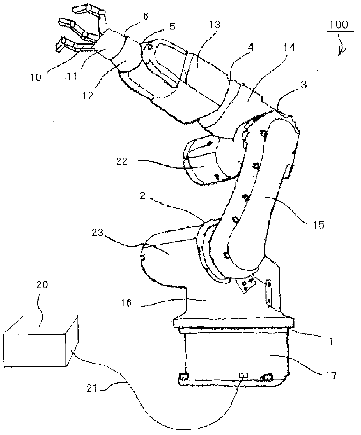
[0036]FIG. 1 is an external perspective view of a robot arm 100 including a communication unit according to a first embodiment. The robot arm 100 includes rotation axes 1 to 6. The robot arm 100 includes a rotating portion 16 which rotates about the rotation axis 1, taking a pedestal 17 as a fixed portion, an arm 15 which rotates about the rotation axis 2, taking the rotating portion 16 as a fixed portion, an arm 14 which rotates about the rotation axis 3, taking the arm 15 as a fixed portion, a rotating portion 13 which rotates about the rotation axis 4, taking the arm 14 as a fixed portion, a rotating portion 12 which rotates about the rotation axis 5, taking the rotating portion 13 as a fixed portion and a manipulator 11 which rotates about the rotation axis 6, taking the rotating portion 12 as a fixed portion.

[0037]The manipulator 11 attaches and removes an object by operating plural fingers 10. The manipulator 11 can be attached and removed at the rotating portion 12 as well as...

second embodiment

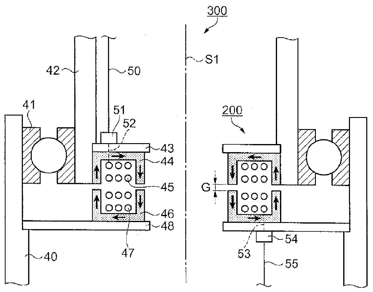
[0060]In a second embodiment, communication transmitted from the fixed side to the rotating side by using two electromagnetic induction coupling portions and, conversely, communication transmitted from the rotating side to the fixed side will be explained. FIG. 6 is a cross-sectional view of a rotating device 300a including a communication unit 200a having two pairs of electromagnetic induction coupling portions.

[0061]The communication unit 200a of FIG. 6 additionally includes a pair of coils 47a, 45a and a pair of magnetic bodies 46a, 44a inside a pair of coils 47, 45 and a pair of magnetic bodies 46, 44 explained in FIG. 2.

[0062]The magnetic bodies 44, 44a including the coils 45, 45a and the magnetic bodies 46, 46a including the coils 47, 47a are supported by supporting members 43a, 48a, respectively.

[0063]A control signal outputted from the controller 20 is transmitted from the fixed side to the rotating side. The signal is transmitted from the communication cable 55 to the commu...

third embodiment

[0071]In a third embodiment, a communication unit including magnetic bodies whose cross-sectional shape covering the inside of the coil is an L-shape will be explained.

[0072]FIG. 7 is a cross-sectional view of a rotating device 300b including a communication unit 200b having magnetic bodies whose cross-sectional shape is an L-shape. In FIG. 7, a pair of magnetic bodies 44, 46 and the supporting members 43, 48 which support them explained in the first embodiment of FIG. 2 are replaced with a pair of magnetic bodies 46b, 44b and supporting members 48b, 43b which support them. As shown in FIG. 7, the cross-sectional shape of a pair of magnetic bodies 46b, 44b is an L-shape, covering the inside of the coil 47 and the coil 45.

[0073]The coil 47 and the magnetic body 46b are fixed by a supporting member 49. When a pulse signal is inputted in the coil 47 or when a pulse signal is induced in the coil 45 by electromagnetic induction coupling, magnetic flux flows in the magnetic bodies 44b, 46...


PUM


Abstract

A rotating device includes a communication unit including a transmitting portion having a first ring-shaped coil, a first ring-shaped magnetic body covering the first ring-shaped coil and a first terminal connected to the first ring-shaped coil, and a receiving portion having a second ring-shaped coil, a second ring-shaped magnetic body covering the second ring-shaped coil and a second terminal connected to the second ring-shaped coil, and a bearing connecting a hollow fixed portion to a hollow rotating portion.

Description

[0001]This is a continuation of U.S. patent application Ser. No. 12 / 392,576 filed Feb. 25, 2009, which claims the benefit of Japanese Patent Application No. 2008-325104 filed Dec. 22, 2008 and Japanese Patent Application No. 2008-049296 filed Feb. 29, 2008. The disclosures of the prior applications are hereby incorporated by reference herein in their entirety.BACKGROUND[0002]1. Technical Field[0003]The present invention relates to a rotating device and a robot arm device.[0004]2. Related Art[0005]In a rotating device including a rotating portion which rotates with respect to a fixed portion, a communication cable in which a signal is transmitted between a fixed side and a rotating side, a power cable to which power is supplied, a flexible pipe through which fluid such as air or liquid flows and the like pass in the vicinity of a rotation axis at which the fixed portion and the rotating portion are connected. In order to suppress a phenomenon in which these cables and flexible pipes ...

Claims


Application Information

Patent Timeline
Patent Type & Authority Applications(United States)
IPC IPC(8): B25J18/00H04B5/00
CPCB25J19/0029B25J19/0041Y10T74/20305Y10T74/20311B25J19/0045
Inventor NAKAJIMA, TAKESHI
Owner SEIKO EPSON CORP
Why Eureka
Try Eureka