Rotating device and robot arm device
a technology of rotating device and rotating arm, which is applied in the direction of mechanical control device, process and machine control, instruments, etc., can solve the problems of difficult to secure a spatial area passing through the inside of the rotation axis, and difficult to allow cables and flexible pipes to pass through the inside of the fixed portion and the rotating portion
- Summary
- Abstract
- Description
- Claims
- Application Information
AI Technical Summary
Benefits of technology
Problems solved by technology
Method used
Image
Examples
first embodiment
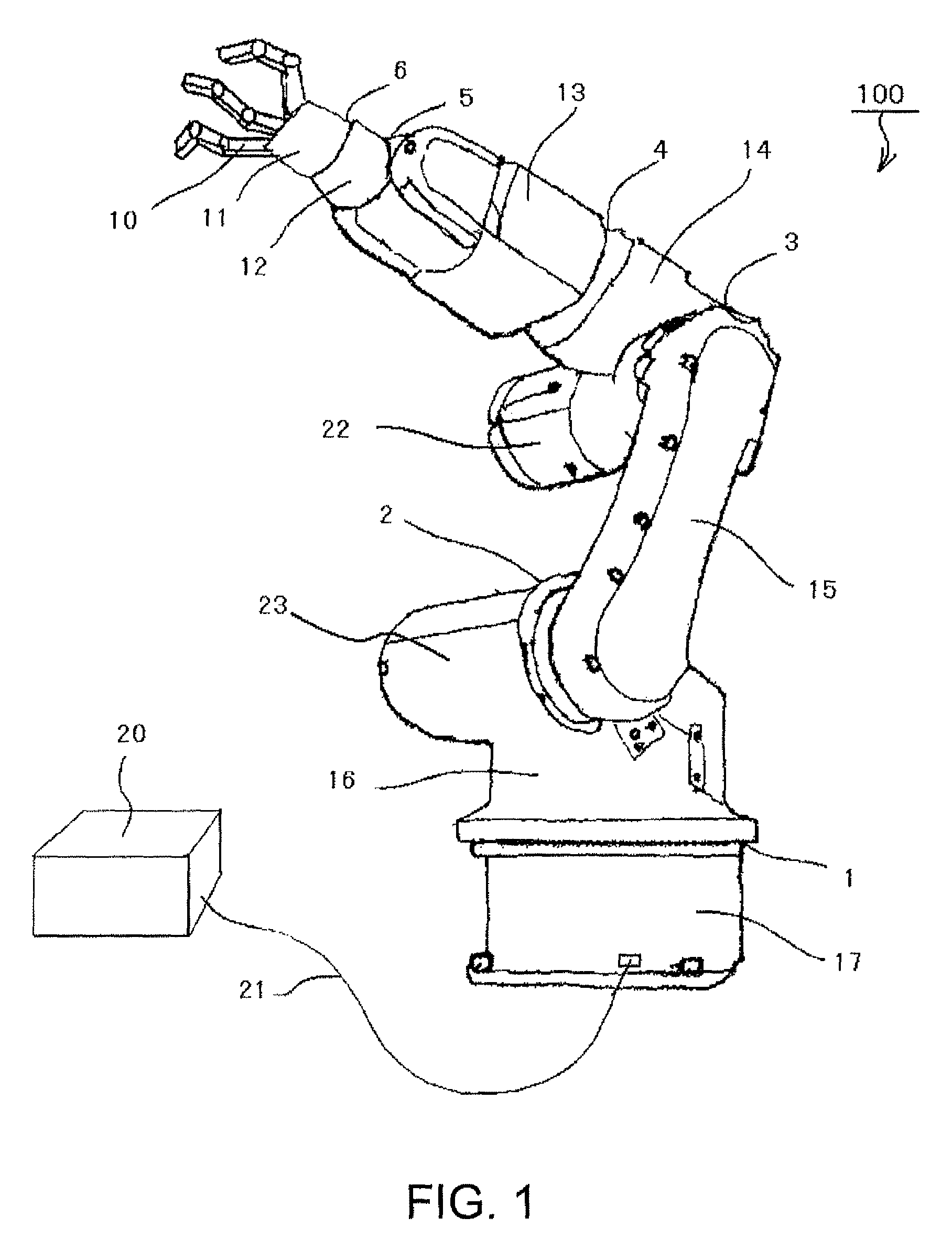
[0035]FIG. 1 is an external perspective view of a robot arm 100 including a communication unit according to a first embodiment. The robot arm 100 includes rotation axes 1 to 6. The robot arm 100 includes a rotating portion 16 which rotates about the rotation axis 1, taking a pedestal 17 as a fixed portion, an arm 15 which rotates about the rotation axis 2, taking the rotating portion 16 as a fixed portion, an arm 14 which rotates about the rotation axis 3, taking the arm 15 as a fixed portion, a rotating portion 13 which rotates about the rotation axis 4, taking the arm 14 as a fixed portion, a rotating portion 12 which rotates about the rotation axis 5, taking the rotating portion 13 as a fixed portion and a manipulator 11 which rotates about the rotation axis 6, taking the rotating portion 12 as a fixed portion.
[0036]The manipulator 11 attaches and removes an object by operating plural fingers 10. The manipulator 11 can be attached and removed at the rotating portion 12 as well as...
second embodiment
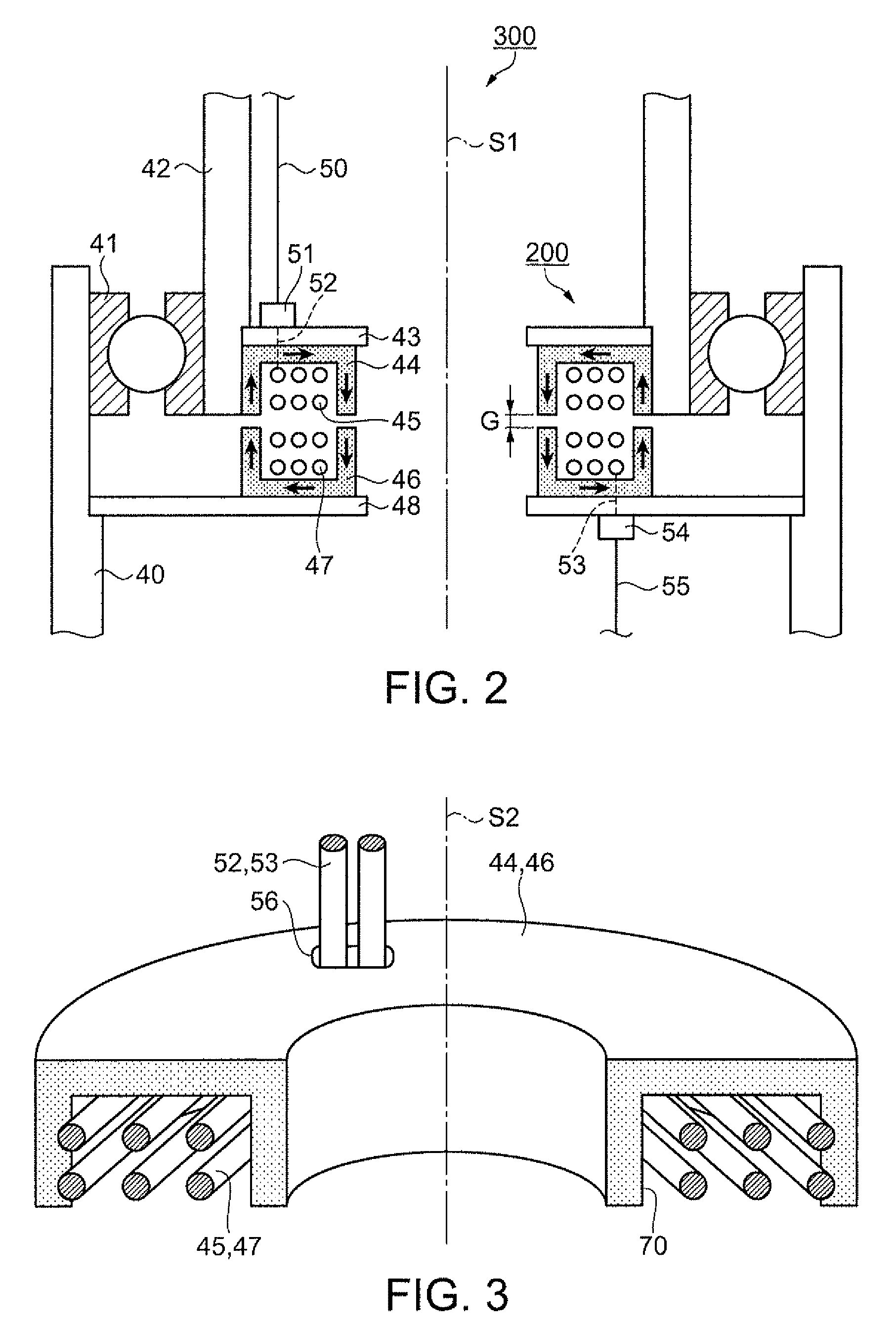
[0059]In a second embodiment, communication transmitted from the fixed side to the rotating side by using two electromagnetic induction coupling portions and, conversely, communication transmitted from the rotating side to the fixed side will be explained. FIG. 6 is a cross-sectional view of a rotating device 300a including a communication unit 200a having two pairs of electromagnetic induction coupling portions.
[0060]The communication unit 200a of FIG. 6 additionally includes a pair of coils 47a, 45a and a pair of magnetic bodies 46a, 44a inside a pair of coils 47, 45 and a pair of magnetic bodies 46, 44 explained in FIG. 2.
[0061]The magnetic bodies 44, 44a including the coils 45, 45a and the magnetic bodies 46, 46a including the coils 47, 47a are supported by supporting members 43a, 48a, respectively.
[0062]A control signal outputted from the controller 20 is transmitted from the fixed side to the rotating side. The signal is transmitted from the communication cable 55 to the commu...
third embodiment
[0070]In a third embodiment, a communication unit including magnetic bodies whose cross-sectional shape covering the inside of the coil is an L-shape will be explained.
[0071]FIG. 7 is a cross-sectional view of a rotating device 300b including a communication unit 200b having magnetic bodies whose cross-sectional shape is an L-shape. In FIG. 7, a pair of magnetic bodies 44, 46 and the supporting members 43, 48 which support them explained in the first embodiment of FIG. 2 are replaced with a pair of magnetic bodies 46b, 44b and supporting members 48b, 43b which support them. As shown in FIG. 7, the cross-sectional shape of a pair of magnetic bodies 46b, 44b is an L-shape, covering the inside of the coil 47 and the coil 45.
[0072]The coil 47 and the magnetic body 46b are fixed by a supporting member 49. When a pulse signal is inputted in the coil 47 or when a pulse signal is induced in the coil 45 by electromagnetic induction coupling, magnetic flux flows in the magnetic bodies 44b, 46...
PUM
 Abstract
Description
Claims
Application Information
 - R&D
- Intellectual Property
- Life Sciences
- Materials
- Tech Scout
- Unparalleled Data Quality
- Higher Quality Content
- 60% Fewer Hallucinations
Browse by: Latest US Patents, China's latest patents, Technical Efficacy Thesaurus, Application Domain, Technology Topic, Popular Technical Reports.
© 2025 PatSnap. All rights reserved.Legal|Privacy policy|Modern Slavery Act Transparency Statement|Sitemap|About US| Contact US: help@patsnap.com


