
Resistance determining system and method for circuit protection

a resistance determination and circuit protection technology, applied in emergency protective circuit arrangements, electrical equipment, parameter calibration/setting, etc., can solve problems such as inefficiency of methods

Inactive Publication Date: 2012-07-19
HONG FU JIN PRECISION IND (SHENZHEN) CO LTD +1
View PDF6 Cites 3 Cited by
  • Summary
  • Abstract
  • Description
  • Claims
  • Application Information

AI Technical Summary

Benefits of technology

The present patent is about a resistance determining system and method for determining resistors in a circuit. The system and method can be used to determine the resistors of an under voltage protection (UVP) circuit in a power circuit. The technical effect of the patent is to provide a more efficient and efficient way to determine the resistors for the UVP circuit, as compared to previous methods that required manual adjustment of resistors. The resistance determining system includes a microcontroller and a digital resistor, which can automatically adjust the resistors to the proper settings for the UVP circuit. This system and method can save time and increase efficiency in the design process of power circuits.

Problems solved by technology

Typical methods usually manually change out different resistors in the UVP circuit to determine the proper resistors for the UVP circuit at the under voltage state and at the voltage recovered state, respectively; this method is inefficient.

Method used


Image

  • Resistance determining system and method for circuit protection
  • Resistance determining system and method for circuit protection
  • Resistance determining system and method for circuit protection

Examples


Embodiment Construction

[0011]Embodiments of the present resistance determining system and method will now be described in detail below and with reference to the drawings.

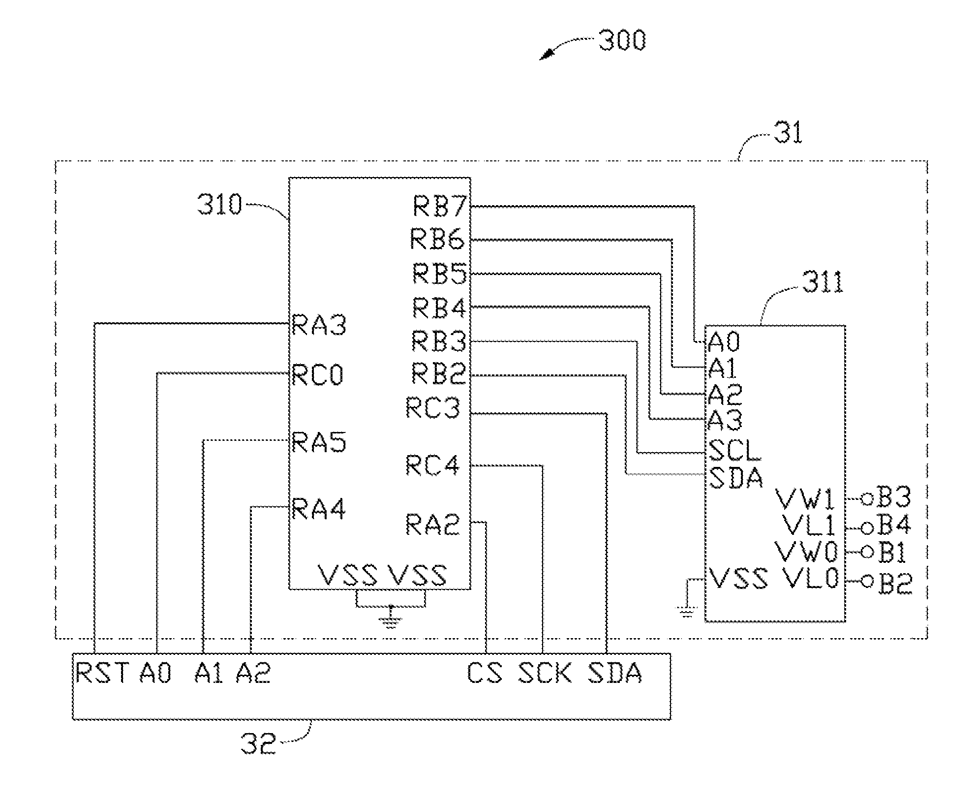
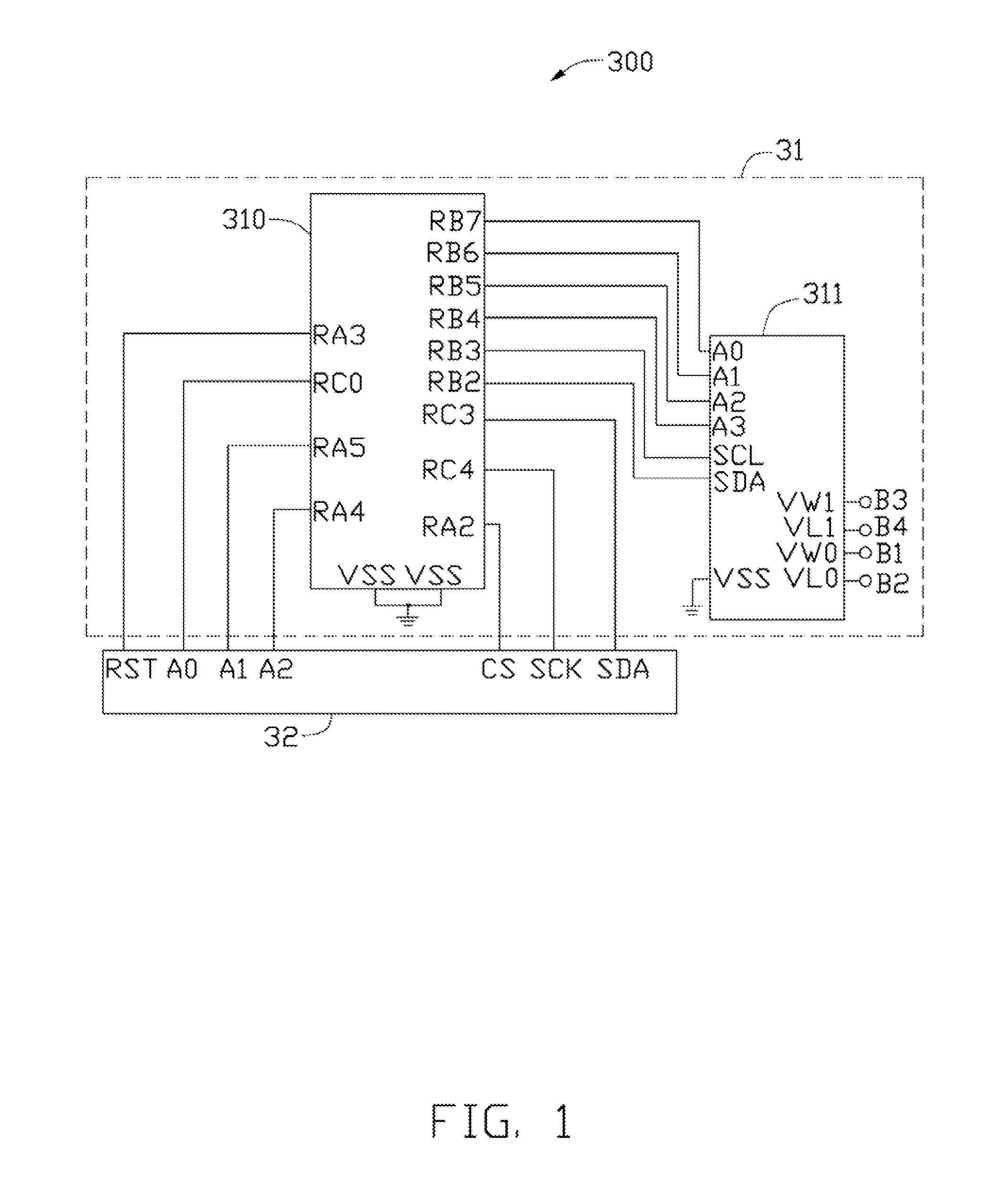
[0012]FIG. 1 is a circuit diagram showing one embodiment of a resistance determining system 300. The system 300 is configured to determine workable resistances for an under voltage protection (UVP) circuit 200 of a power circuit 100 (shown in FIG. 2). The workable resistances include a resistance of an input resistor 201 of the UVP circuit 200 at an under voltage state, and a resistance of a responsive resistor 202 of the UVP circuit 200 at a voltage recovered state.

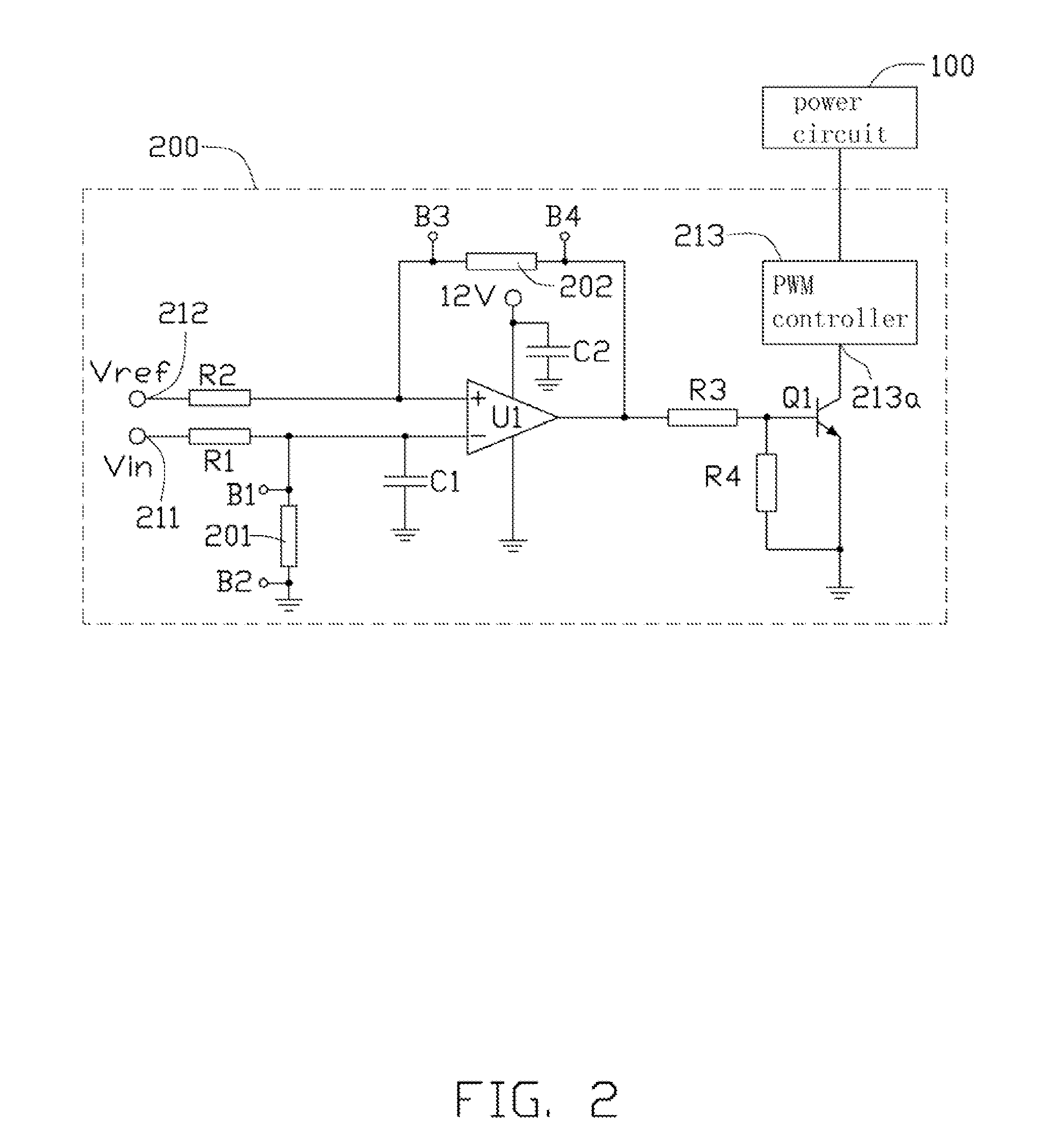
[0013]Referring to FIG. 2, the UVP circuit 200 of the power circuit 100 includes a first voltage input end 211 connected to an external voltage Vin, a second voltage input end 212 connected to a reference voltage Vref. The UVP circuit 200 is configured to interconnect a first terminal B1 and a second terminal B2 nearest to the input resistor 201, a third terminal B3 and a four...


PUM


Abstract

A resistance determining system and method for a protection circuit, includes a resistance determining unit. The resistance determining unit interconnects a microcontroller and a digital resistor, where the microcontroller has first setting voltage corresponding to a first voltage threshold for activating the protection circuit, and the microcontroller is capable of receiving and converting a first external voltage input to the protection circuit to be a first converted voltage. The digital resistor includes a first variable resistor having two terminals connected to the respective first terminal and the second terminal. The microcontroller adjusts a resistance of the first variable resistor to be a first threshold resistance if the first converted voltage is substantially equal to the first voltage threshold, and the first resistance is determined to be substantially equal to the first threshold resistance.

Description

BACKGROUND[0001]1. Technical Field[0002]The present disclosure relates to a resistance determining systems and methods, and particularly to a resistance determining system and method for determining resistances for circuit protection.[0003]2. Description of Related Art[0004]Power circuits for various electronic devices usually have protection circuits, such as an under voltage protection (UVP) circuit. When an input voltage is at an under voltage state, the UVP circuit controls the power circuits to turn off, and when an input voltage is at a recovered state, the power circuits can turn on. The UVP circuit needs resistors, usually called input resistors and responsive resistors, to support the its work at the under voltage state and at the voltage recovered state, respectively.[0005]The resistances of the input resistor and the responsive resistor have to be determined in designing the UVP circuit. Typical methods usually manually change out different resistors in the UVP circuit to...

Claims


Application Information

Patent Timeline
Patent Type & Authority Applications(United States)
IPC IPC(8): H02H3/24
CPCH02H3/24H02H3/006
Inventor TONG, SONG-LINLUO, QI-YANCHEN, PENG
Owner HONG FU JIN PRECISION IND (SHENZHEN) CO LTD
Learn More