
Solar tracker for the orientation of solar panels

Inactive Publication Date: 2012-07-19
INDRA SISTEMAS
View PDF2 Cites 5 Cited by
  • Summary
  • Abstract
  • Description
  • Claims
  • Application Information

AI Technical Summary

Benefits of technology

[0019]Another advantage of the invention tracker is that its component parts are simple and easy to replace, which facilitates the management of procurement and spare part logistics.
[0020]Other features and advantages of this invention will be deduced from the following detailed description of an illustrative embodiment of its object in relation to the accompanying figures.

Problems solved by technology

These configurations that need a stationary vertical pole, and in which the azimuth rotation around a vertical axis is achieved by various sorts of mechanisms, require constant maintenance and a laborious mounting process, and on many occasions that are also sensitive to oscillations.

Method used


Image

  • Solar tracker for the orientation of solar panels
  • Solar tracker for the orientation of solar panels
  • Solar tracker for the orientation of solar panels

Examples


Embodiment Construction

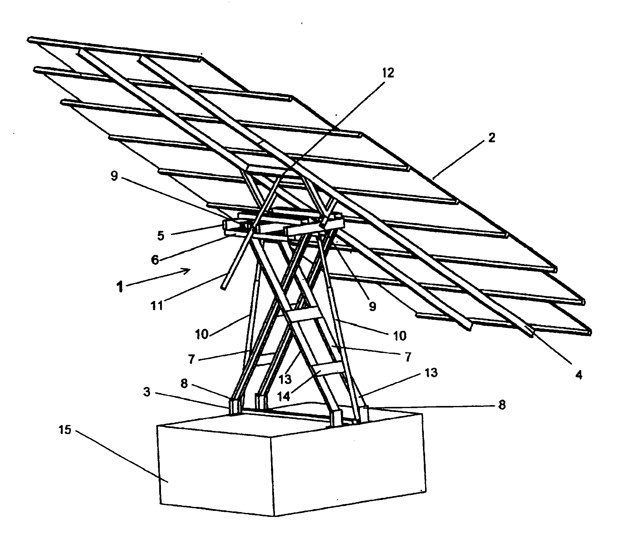
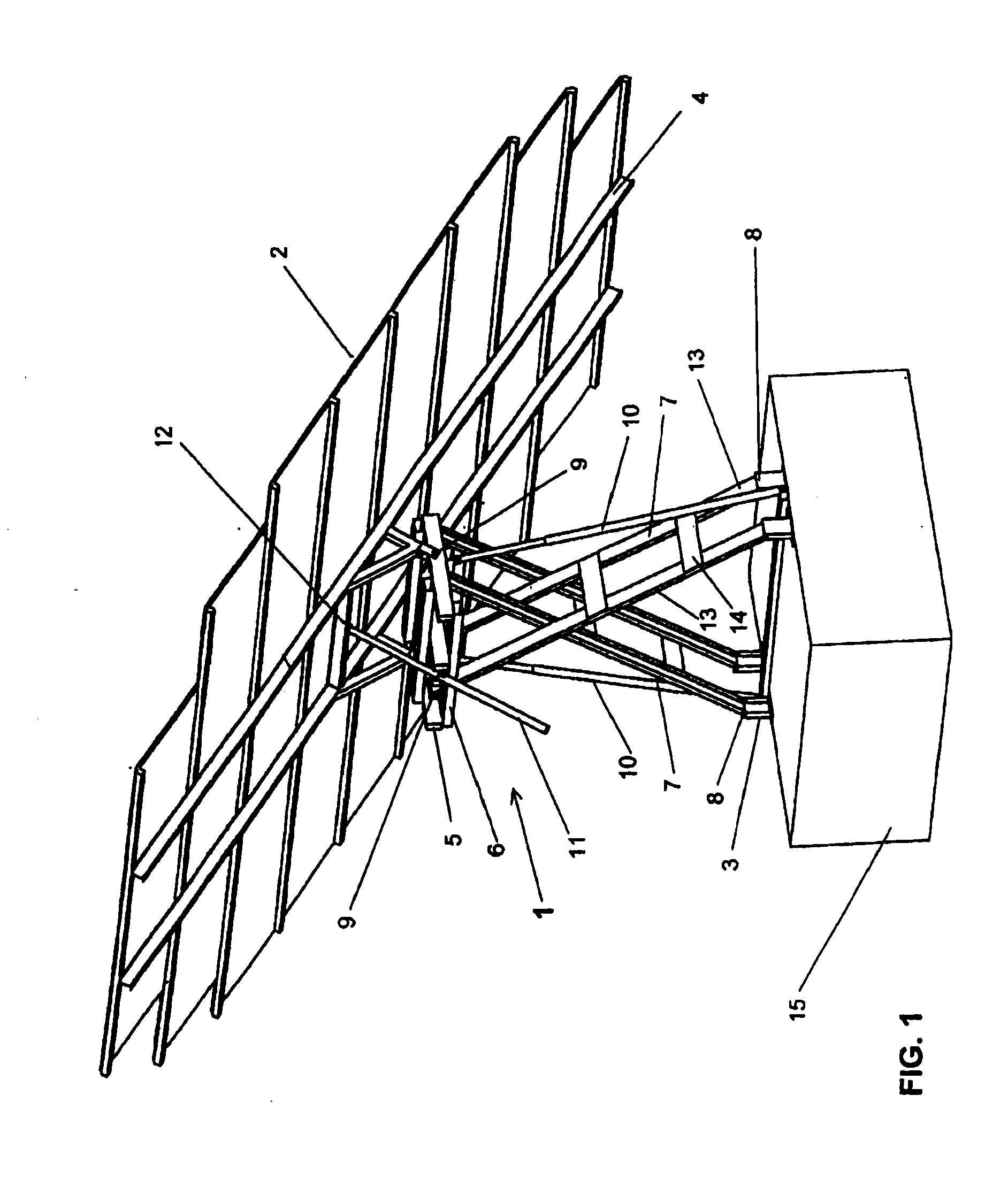
[0030]is FIG. 1 shows a view in perspective of a solar tracker 1 of the invention with solar plates 2 attached, in an initial position. The solar tracker 1 is supported on a base 3 (in this case with a support platform 15), and its upper part comprises a holding structure 4 for the solar panels 2, which supports them. FIG. 1 also shows that there is an intermediate support element 5 underneath the holding structure 4, to which the latter is articulated.

[0031]The holding structure 4 (and, therefore, the solar panels 2) are able to follow the sun in both elevation and azimuth, so that the surfaces of the solar panels 2 are permanently oriented perpendicularly to the solar rays. For this purpose, the solar tracker 1 is provided with two mechanisms:[0032]a) a first mechanism that produces a flat movement and that comprises three mobile rigid elements—one central 6 and two lateral 7—with the two rigid lateral elements 7 hinged to the base 3 at one end 8 and to the rigid central element 6...


PUM


Abstract

Solar tracker (1) for the orientation of solar panels (2), which is supported on a base (3) and comprises a holding structure (4) for the solar panels (2). It comprises an intermediate support element (5) to which the holding structure (4) of the panels (2) is articulated. The two movements of the holding structure (4) of the panels (2) are respectively produced by:a) a first mechanism that produces a flat movement, with three mobile rigid elements—one central (6) and two lateral (7). The rigid lateral elements (7) can be moved by means of linear actuators (10). The intermediate support element (5) can be on one of the mobile rigid elements (6, 7) or be coincident with it, andb) a second mechanism that acts on the holding structure (4) and is located on the intermediate support element (5); it comprises means to make the holding structure (4) rotate around an axis integral with the intermediate support element (5).

Description

FIELD OF THE INVENTION[0001]This invention refers to a solar tracker of the kind used to keep solar plates or panels perpendicularly oriented towards the solar rays and in this way optimise the collection of solar energy.BACKGROUND OF THE INVENTION[0002]The panels for solar energy-based production are mounted on structures oriented towards the sun. These structures can be either stationary or mobile. Stationary structures are simple frames on which the panels are arranged with an orientation that does not vary.[0003]To maximise electric power production, different systems have been developed to orient the panel so that the radiation strikes perpendicularly to the panel. Two degrees of freedom would be required to target the sun at any hour and on any day of the year. These degrees of freedom usually correspond to the angle of elevation of the sun and the azimuth angle. The elevation is usually achieved by rotating the panel with respect to a horizontal axis, which is usually done wi...

Claims


Application Information

Patent Timeline
IPC IPC(8): H01L31/052F24S50/20
CPCF24J2/5424F24J2002/5441F24J2002/5455Y02E10/47F24J2002/5465F24S30/455F24S2030/132F24S2030/135F24S2030/115F24S50/20F24S30/45
Inventor GONZALEZ RODRIGUEZ, ANTONIOGONZALEZ RODRIGUEZ, ANGEL GASPARCAMINERO TORIJA, MIGUEL ANGELCHACON MUNOZ, JESUS MIGUELGARCIA MARQUEZ, FAUSTO PEDRO
Owner INDRA SISTEMAS
Learn More