
Large volume pipette tip for loading in an automated liquid handler

a technology of automated liquid handler and pipette tip, which is applied in the direction of laboratory glassware, instruments, chemistry apparatus and processes, etc., can solve the problems of reducing the efficiency and productivity of the lab or other facility, and the inability to use the micropipetting system, and achieve the effect of high speed

Inactive Publication Date: 2012-07-19
PERKINELMER HEALTH SCIENCES INC
View PDF1 Cites 14 Cited by
  • Summary
  • Abstract
  • Description
  • Claims
  • Application Information

AI Technical Summary

Benefits of technology

[0007]The present disclosure is directed toward pipette tips for use with automated liquid dispensing equipment. In particular, the present disclosure is directed toward pipette tips adapted to provide for simultaneous, large volume pipetting with several tips positioned in close proximity to each other, allowing for high speed, multi-well dispensing, even where the wells in a tray are extremely close to each other. Embodiments of the pipette tip have a long, narrow tip with a tapered end that can provide access to the full volume in a narrow tube or the bottom of a deep-well block. Embodiments of the pipette tip also can be impregnated with carbon material, allowing the tip to be used in liquid level detection systems.

Problems solved by technology

When a large volume of fluid (i.e., a volume approaching 5 mL or more) is to be measured or dispensed, a micropipetting system cannot be used, as the tips, being used to fill wells spaced on 9 mm centers, often are too narrow to hold enough liquid.
Apparatus configuration changes such as these reduce the efficiency and productivity of the lab or other facility.

Method used


Image

  • Large volume pipette tip for loading in an automated liquid handler
  • Large volume pipette tip for loading in an automated liquid handler
  • Large volume pipette tip for loading in an automated liquid handler

Examples


Embodiment Construction

[0022]The present disclosure is directed toward pipette tips adapted to be used with micropipetting apparatus to simultaneously dispense large volumes of fluids into a plurality of wells in a microplate, and for methods and systems related to the same. This specification and the associated drawings illustrate and describe several specific embodiments of such devices, systems and methods. The inventors appreciate that one of ordinary skill in the art, having reviewed this disclosure in its entirety, will appreciate that changes could be made to the details provided and illustrated in this disclosure, and that details could be eliminated from particular embodiments, all without causing the resultant embodiment to deviate from the present invention.

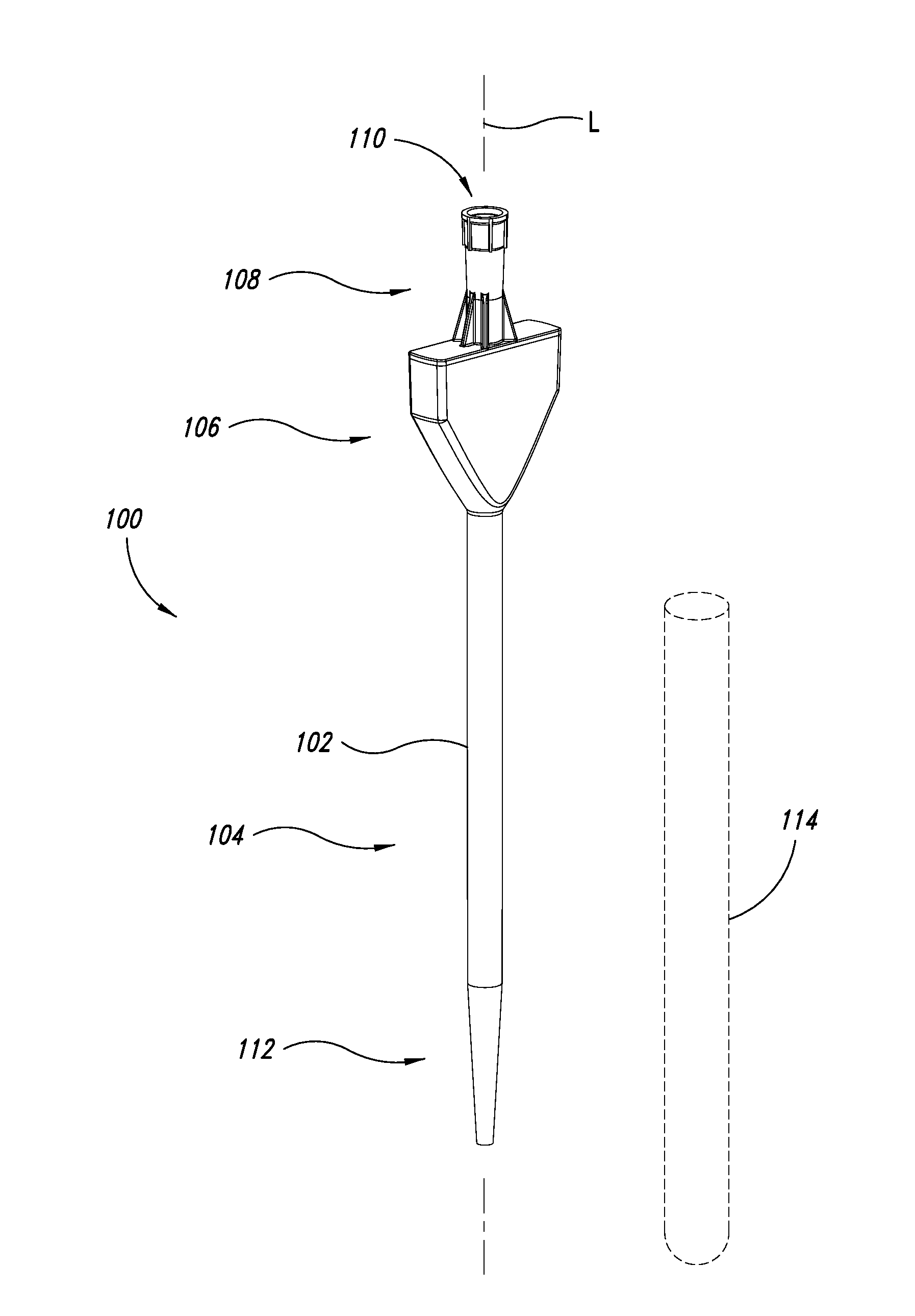
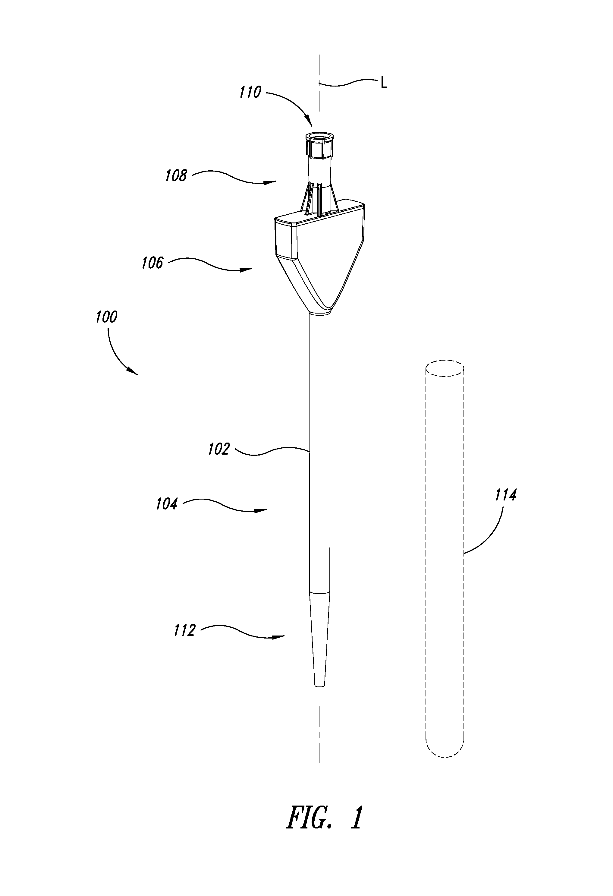
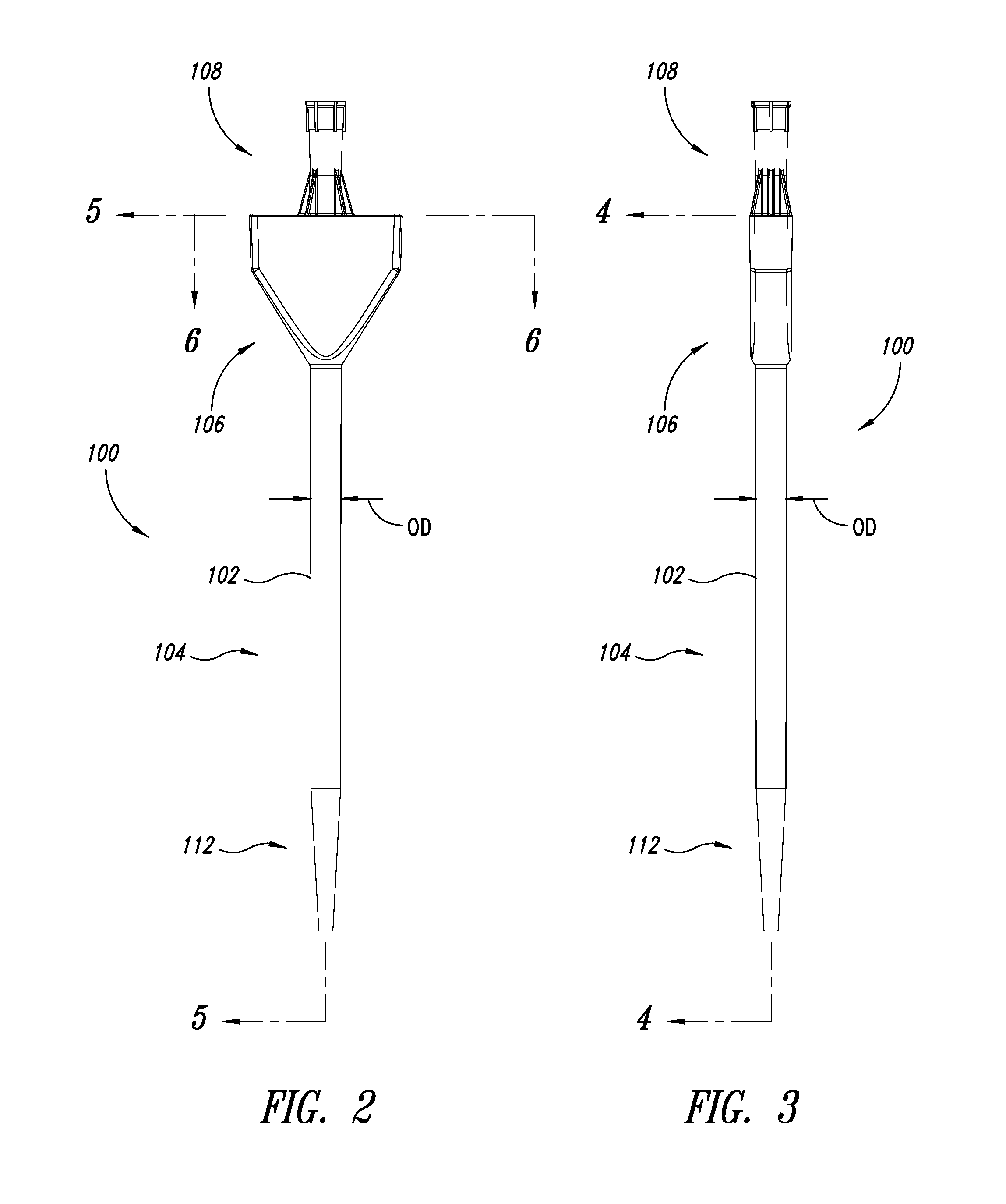
[0023]FIGS. 1-3 illustrate one particular embodiment of a pipette tip 100 for simultaneous use with a plurality of other such pipette tips to dispense large volumes of fluids. The illustrated pipette tip 100 has a body 102 with a lower porti...


PUM


Abstract

A pipette tip having lower, upper and central portions and a bore extending therethrough. The lower portion is elongated and projects in a first direction from the central portion, and is sized and shaped for insertion into a test-tube. The bore is adapted for aspirating and dispensing a large volume of the liquid. The upper portion projects from the central portion in a second direction opposing the first direction, and its terminal end is sized and shaped to sealingly engage an automated pipetting system. The central portion and a corresponding portion of the bore are enlarged with respect to both the upper and lower portions to allow the pipette tip to hold the large volume of the liquid. The central portion can have a cross-section substantially rectangular in shape. The cross-section can have a height at least substantially similar to the diameter of the lower portion of the pipette tip and a width significantly greater than the diameter of the lower portion of the pipette tip.

Description

BACKGROUND OF THE INVENTION[0001]1. Field of the Invention[0002]The present disclosure is related to pipette tips and, more particularly, to large volume pipette tips, and to systems and methods incorporating the same.[0003]2. Description of the Related Art[0004]As micropipetting has become common, more and more labs and other facilities are using automated micropipetting systems. A microplate with 96 wells on 9 mm centers in an 8 well by 12 well array is often used with dispense apparatus. Early prior art dispense devices used one dispenser and moved the dispenser in the X-Y direction 96 times to dispense into each of the 96 wells. Because only one tip is used in such a system, there was nothing at the time restricting the diameter of the tip. As a result, the tips could have as large a diameter as necessary to hold the desired volume of liquid.[0005]Over time, however, dispense apparatus were developed to dispense an entire row at one time, indexed to fill the entire plate. Appara...

Claims


Application Information

Patent Timeline
IPC IPC(8): B01L3/02
CPCB01L3/0275B01L2200/087G01N2035/103G01N35/1065B01L2300/0858
Inventor BRADY, LEESCHOELL, LARRYMILLARD, GARY V.CLOUTIER, TIMOTHY E.
Owner PERKINELMER HEALTH SCIENCES INC
Learn More