
Conformal Hybrid EO/RF Aperture

a hybrid, electrooptical/radio frequency technology, applied in particular array feeding systems, line-of-sight transmission, electromagnetic transmission, etc., can solve the problems of conformal systems and large volume, and achieve optimized rf performance, good impedance match, and optimized aperture efficiency

Active Publication Date: 2012-07-12
RAYTHEON CO
View PDF7 Cites 33 Cited by
  • Summary
  • Abstract
  • Description
  • Claims
  • Application Information

AI Technical Summary

Benefits of technology

[0013]In one embodiment, the low-band aperture is capable of steering an RF beam about fifty (50) degrees in any elevation direction without using a conventional elevation-over-azimuth gimbal. The hybrid system described herein allows the OPA to be located in the middle of the HERA and rotated together in azimuth with a common turntable.
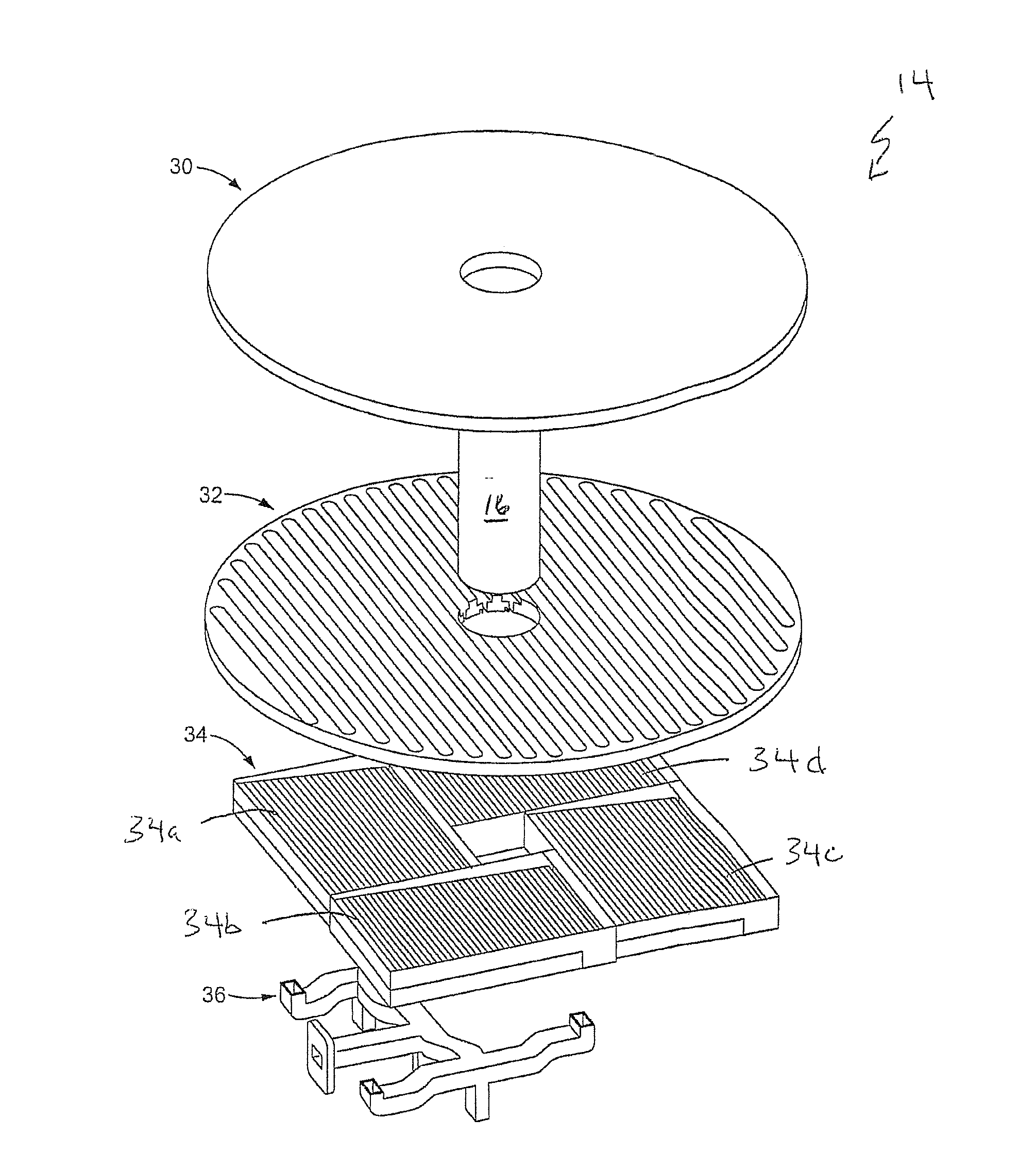
[0015]In one embodiment, four CTS subarrays are used. The four subarray aperture configuration surrounds the OPA while also providing optimized RF performance (optimized in terms of aperture efficiency and good impedance match for wide angle scan). This configuration makes it possible for the RF aperture and OPA to have a common azimuth rotation axis and could be rotated using a common azimuth turntable. It also avoids loss of RF energy in the blockage area occupied by the OPA.
[0016]In one embodiment, the subarrays have a rectangular shape and comprise slow-wave corrugations. The slow-wave corrugations of the rectangular subarrays coupled to the radiating slots of an upper rotating slot plate provide the antenna having improved, and in some cases optimized, antenna efficiency. The radiating slot design is optimized for two different slow-wave structures. In one embodiment, the antenna comprises a radome disposed over the VICTS antenna. The radome has an opening therein to expose the OPA.

Problems solved by technology

However, neither system is conformal and both require significant volume.

Method used


Image

  • Conformal Hybrid EO/RF Aperture
  • Conformal Hybrid EO/RF Aperture
  • Conformal Hybrid EO/RF Aperture

Examples


Embodiment Construction

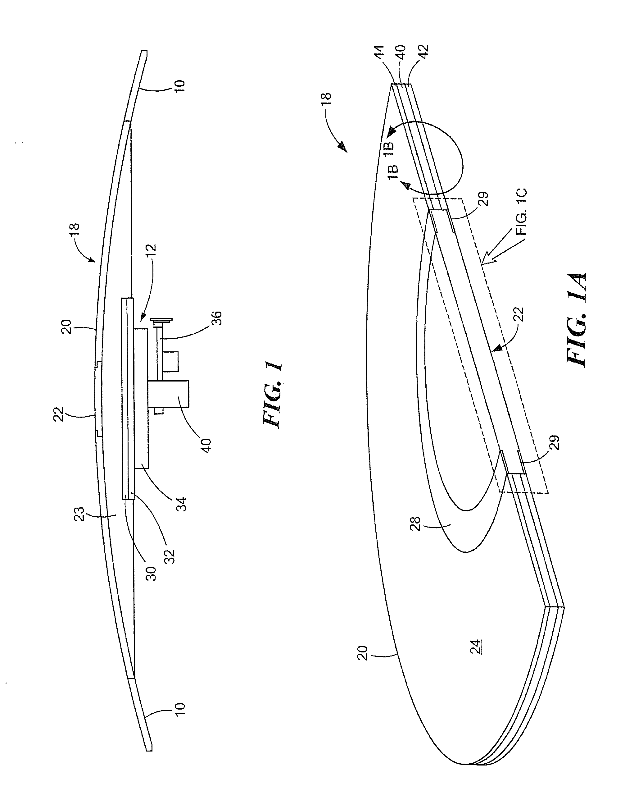
[0031]Referring now to FIG. 1, a body 10 has an opening therein in which is disposed a conformal hybrid electro-optic / radio frequency (EO / RF) aperture (HERA) 12.

[0032]Body 10 may correspond, for example, to a fuselage or other portion of an aircraft or unmanned aerial vehicle (UAV) or to a portion of a ground based vehicle, such as a truck or to a portion of a ship or a ground based station or other ground-based, air-based or water-based body.

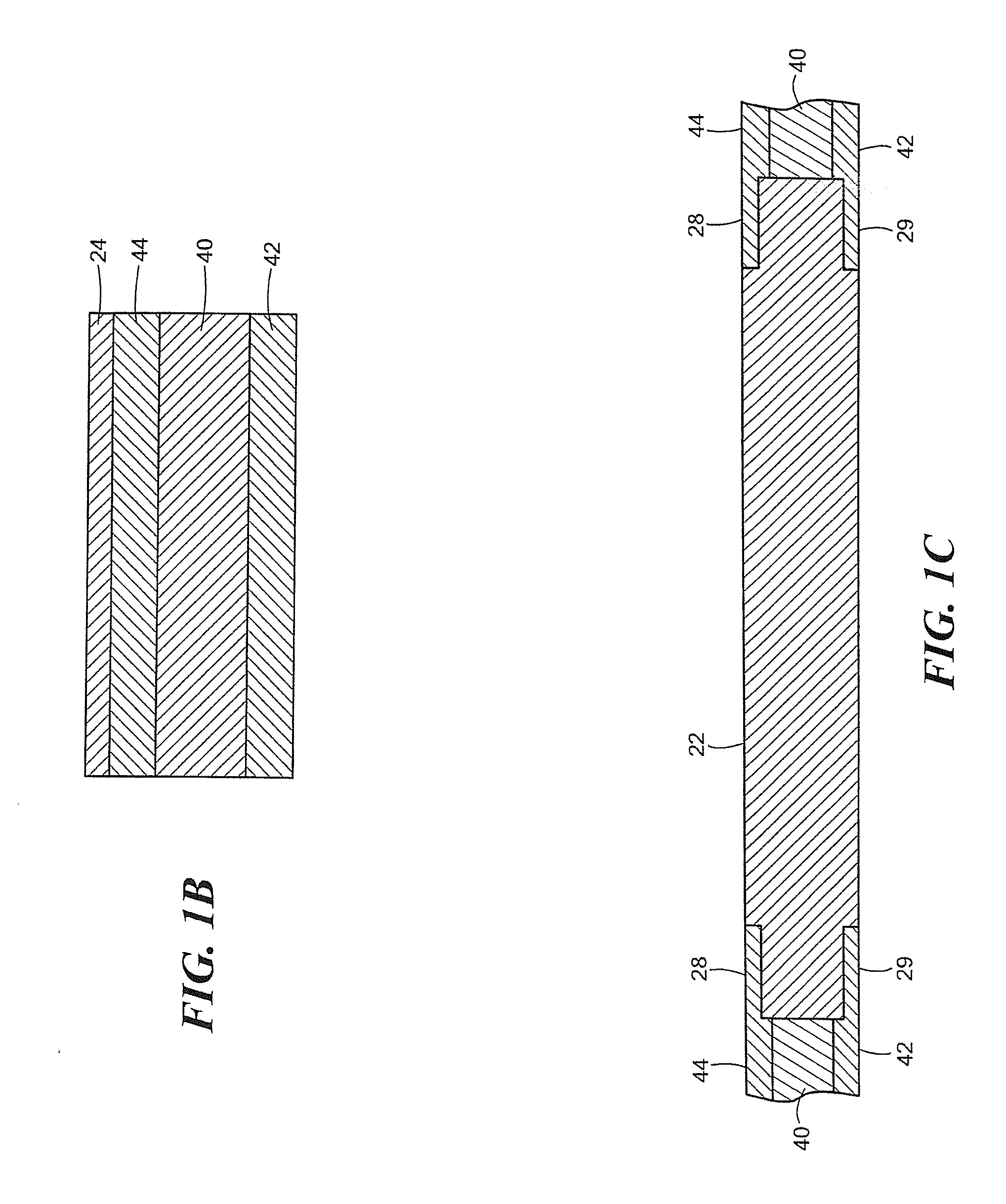
[0033]Hybrid EO / RF aperture 12 is provided from a variable inclination continuous transverse stub (VICTS) antenna 14 having an aperture in a central portion thereof in which is disposed an optical phased array (OPA) 16. An integrated window 18 is disposed over the VICTS antenna. Integrated window 18 includes an RF radome portion 20 and an optical window portion 22 which together provide window 18 as an integrated window 18. An OPA signal can only pass through optical window but not the RF radome. It should be noted that the OPA aperture is sign...


PUM


Abstract

A conformal hybrid elctro-optical / radio frequency (EO / RF) aperture including an optical phased array (OPA) in a center portion of the aperture, and a variable inclination continuous transverse stub (VICTS) RF antenna surrounding the OPA using a plurality of continuous transverse stub (CTS) subarrays.

Description

CROSS REFERENCE TO RELATED APPLICATION[0001]This application claims the benefit of U.S. Provisional Application No. 61 / 373,307 filed Aug. 13, 2010 under 35 U.S.C.§119(e) which application is hereby incorporated herein by reference in its entirety.FIELD OF THE INVENTION[0002]The system and techniques described herein relate generally to antennas and optical phased arrays, and more particularly to a conformal hybrid electro-optical / radio frequency (EO / RF) aperture.BACKGROUND OF THE INVENTION[0003]As is known in the art, there is a need for transferring relatively large amounts of data (>1 Gb / sec) between satellite / sensors, unmanned aerial vehicle (UAVs), aircrafts, ships and ground. Potential applications include airborne networking backbone for GIG extension and US Navy high data rate reach-back for military, downloading of satellite gathered data for NASA / NOAA, and border monitoring or disaster recovery communications for homeland security.[0004]To satisfy the requirements of suc...

Claims


Application Information

Patent Timeline
Patent Type & Authority Applications(United States)
IPC IPC(8): H04B10/10H01Q5/22H01Q5/28
CPCH04B10/112H01Q1/281H01Q1/425H01Q3/04H01Q3/12H01Q13/22H01Q5/28H01Q15/24H01Q21/0031H01Q5/0013H01Q5/002H01Q5/22H01Q13/28
Inventor CHANG, YUEH-CHIPORTER, BRADLEY G.FAGERLUND, GREGORY M.BENNETT, LEONARD C.SIKINA, THOMAS V.MUI, BRANDON K.
Owner RAYTHEON CO
Learn More