
Coding and decoding of source signals using constrained relative entropy quantization

a relative entropy and quantization technology, applied in the field of quantizing signals, can solve the problems of increasing the mean square error, rather than circumventing the problem, and reducing the processing efficiency of source signals, so as to reduce the noise of quantization, alleviate or eliminate one or more of the above-mentioned deficiencies and drawbacks, and reduce the effect of quantization nois

Active Publication Date: 2012-07-12
GOOGLE LLC
View PDF2 Cites 9 Cited by
  • Summary
  • Abstract
  • Description
  • Claims
  • Application Information

AI Technical Summary

Benefits of technology

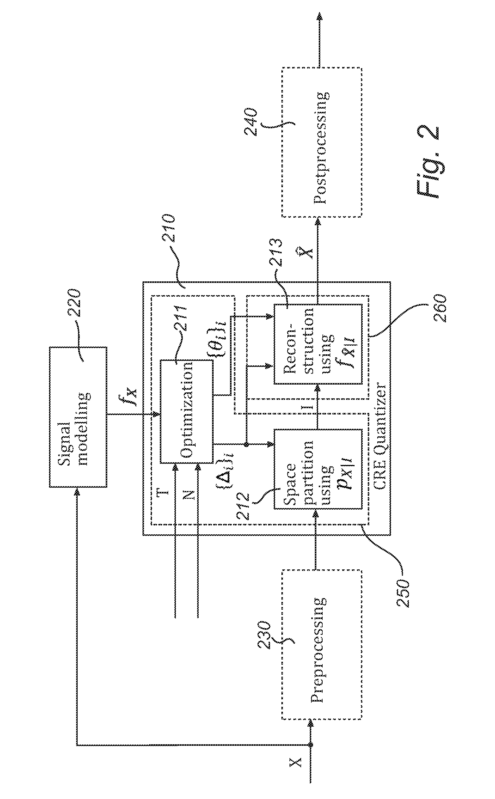
[0013]determining, in part, a partition into quantization cells by minimizing the quantization error subject to a constraint on a measure of the difference between the estimated probability distribution of the source signal and the reconstruction distribution; and
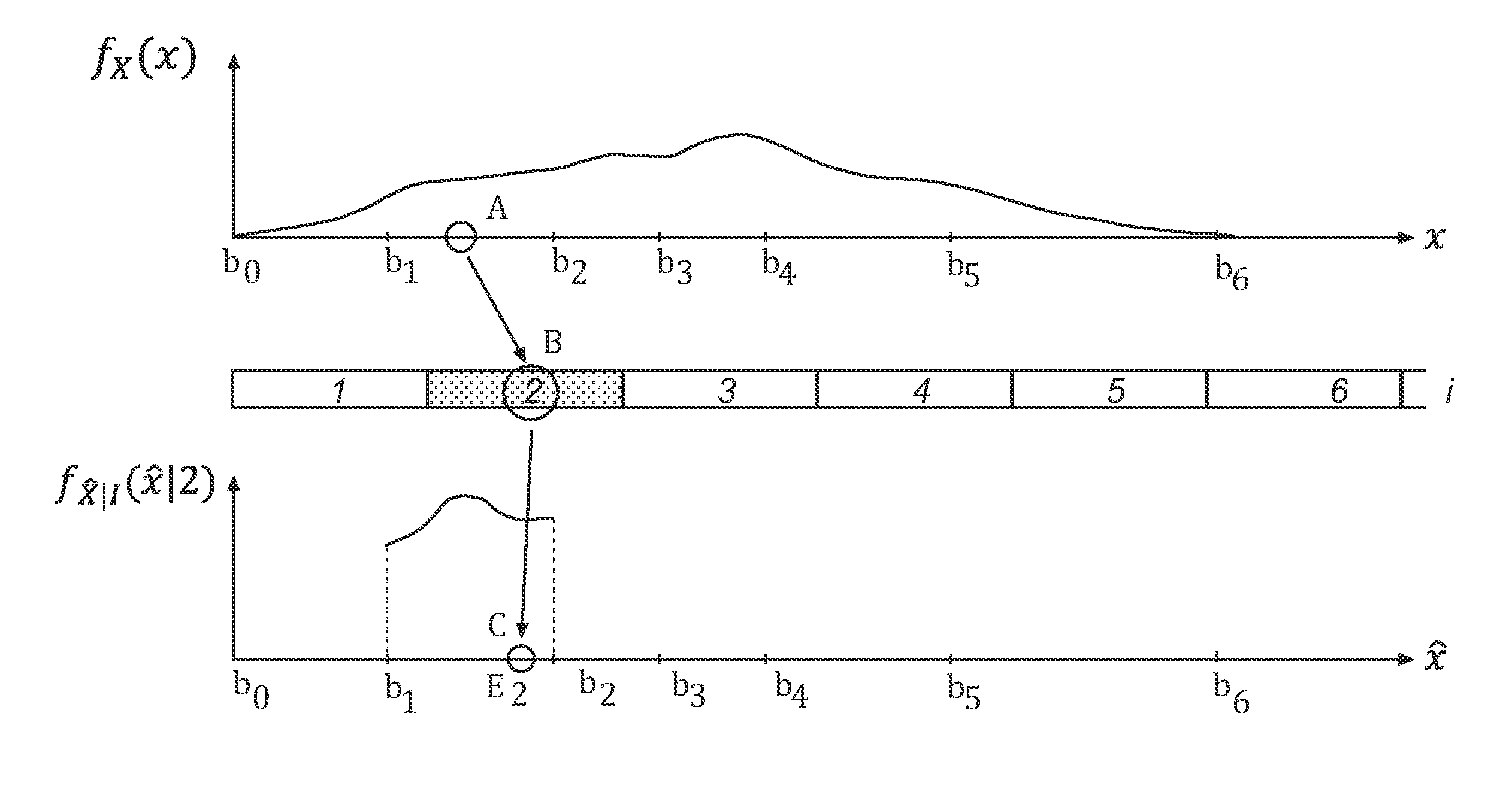
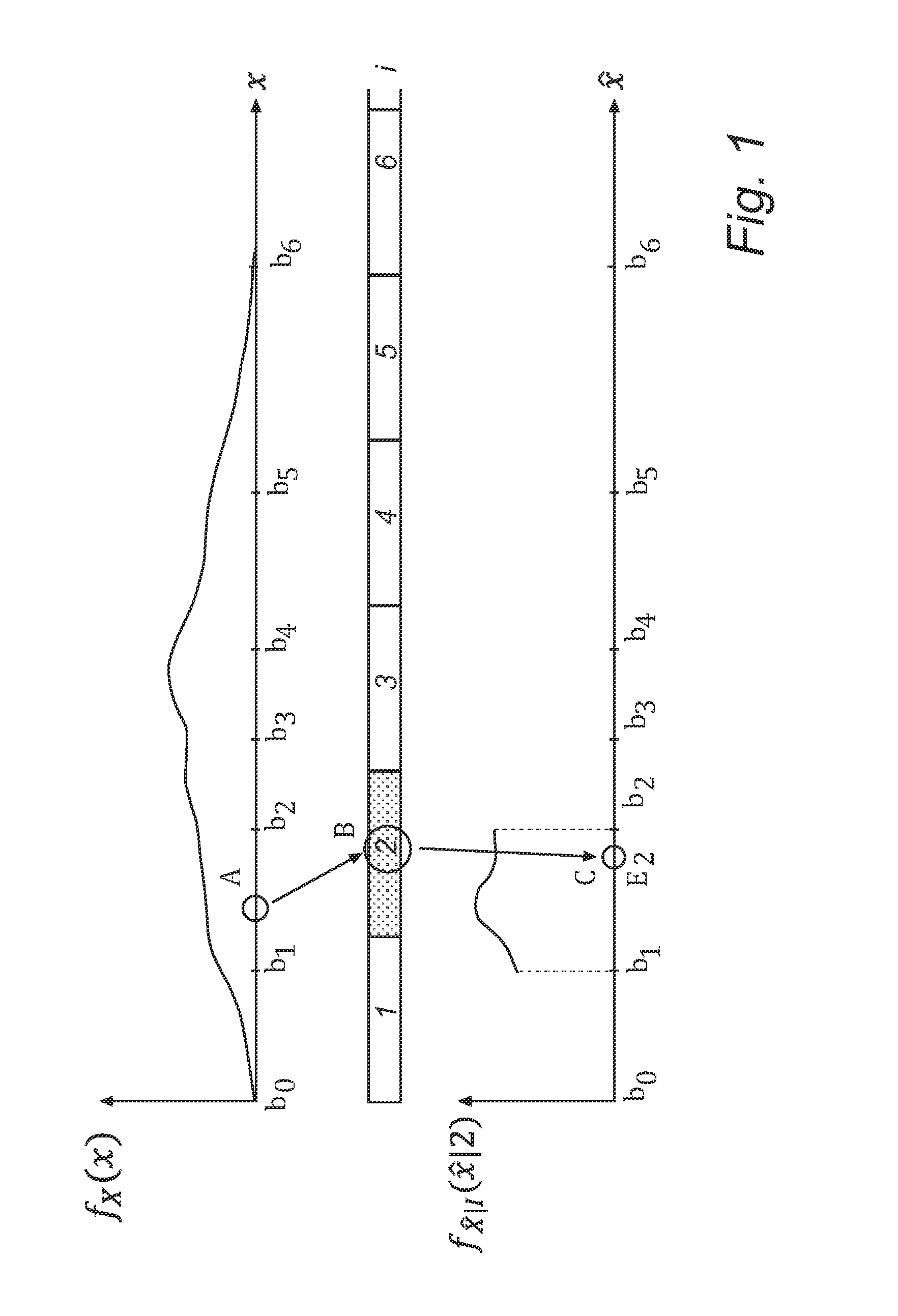
[0022]One embodiment of the invention includes using an estimated probability distribution of the source signal and using a reconstruction probability distribution corresponding to this distribution. In particular, the reconstruction probability distribution may be an approximation of the estimated probability distribution of the source signal. To illustrate this in the case of the ith quantization cell, the reconstructed signal value is a random sample from a stochastic variable, whose probability distribution approximates the estimated probability distribution of the source signal conditioned on the source signal value falling in the ith cell. In practice, this can be achieved by sampling from a distribution that vanishes outside the ith quantization cell. Quantization according to this embodiment is adapted to preserve the distribution of the source signal. In addition to preserving the distribution of the source signal, variants of this embodiment may further provide quantization that is optimal as far as the mean squared quantization error is concerned.
[0025]In still another embodiment, the partition into quantization cells and / or the reconstruction probability distribution are determined in such manner that the quantization error is minimized subject to a bit-rate condition and constraint on the relative entropy between the estimated probability distribution of the source signal and the reconstruction distribution. More precisely, the bitrate condition is an upper bound on the theoretical minimum bit rate required for transmission or storage. As will be further elaborated on below, this embodiment has produced excellent empirical results.

Problems solved by technology

However, at least if a moderate number of reference levels are applied, perceptible quantization noise and artefacts may occur in the reconstructed signal.
However, considering that expected savings in bandwidth and storage is one of the main motivations for quantization, this rather circumvents than solves the problem.
Dithering, that is, adding stochastic noise in connection with the reconstruction of the signal, may improve the audible impression, even though it increases the mean squared error.
Indeed, it has been established that some artefacts are associated with an unintended statistical correlation between the quantization error and the source signal value, which all the more perceptible the more the error repeats.
The dithering noise however alienates the source signal from the reconstructed signal in terms of probability densities, and there is no theoretical upper bound on the difference.
On the one hand, it is well-known that low-rate video coding results in artifacts such as blurriness, ringing, and blocking.
However, high-quality parametric models do not provide an exact description of the original image and no certainty exists about their perceived accuracy.

Method used


Image

  • Coding and decoding of source signals using constrained relative entropy quantization
  • Coding and decoding of source signals using constrained relative entropy quantization
  • Coding and decoding of source signals using constrained relative entropy quantization

Examples


embodiment 1

2. A method , further including:

[0082]receiving an estimated probability distribution of the source signal,

[0083]wherein the reconstruction probability distribution corresponds to the estimated probability distribution of the source signal.

3. A method according to embodiment 1, further including:

[0084]receiving an estimated probability distribution of the source signal; and

[0085]determining said reconstruction probability distribution based on the estimated probability distribution of the source signal and in such manner that a quantization error is minimized.

4. A method according to embodiment 1, wherein said quantization cells are delimited by values b0, b1, b2, . . . , bM and the reconstruction probability distribution is proportional to [θi(x−Ei)2−1]−1 in the ith cell,

[0086]where Ei denotes a conditional expectation of the source signal in the ith cell, and b0, b1, . . . , bM, θ1, θ2, . . . , θM are solutions of

minb0,b1,…,bM,θ1,θ2,…,θMDsubjecttoK_<TandR<N,

where D denotes a...

embodiment 5

6. A decoder ,

[0089]further comprising a second receiving section for receiving an estimated probability distribution of the source signal,

[0090]wherein the random number generator is adapted to use a reconstruction probability distribution corresponding to the estimated probability distribution of the source signal.

7. A decoder according to embodiment 5, further comprising:

[0091]a second receiving section for receiving an estimated probability distribution of the source signal; and

[0092]means for determining said reconstruction probability distribution based on the estimated probability distribution of the source signal and in such manner that a quantization error is minimized.

8. A decoder according to embodiment 5, wherein said quantization cells are delimited by values b0, b1, b2, . . . , bM and the reconstruction probability distribution is proportional to [θi(x−Ei)2−1]−1 in the ith cell,

[0093]where Ei denotes a conditional expectation of the source signal in the ith cell, and b...

embodiment 10

11. A method , wherein said measure of the difference between the estimated probability distribution of the source signal and the reconstruction distribution is a relative entropy between the estimated probability distribution of the source signal and the reconstruction probability distribution.

12. A computer-readable medium having stored thereon computerreadable instructions which, when executed on general-purpose computer, perform the method of any one of embodiments 1 to 4, 10 and 11.

13. A method according to any one of embodiments 1 to 4 and 10 to 12, wherein source signal values and quantization indices are n-dimensional vectors, n being an integer greater than 1.

14. An encoder (250) for encoding a source signal consisting of a sequence of source signal values, the encoder including:

[0097]an optimizing section (211) adapted to receive an estimated probability distribution of the source signal and to determine, in part, a partition into quantization cells by minimizing the quant...


PUM


Abstract

Methods and devices for encoding and decoding are provided. A source signal value is encoded by a quantization index determined using a partition into quantization cells. Decoding of the quantization index takes place by sampling a reconstruction probability distribution, thereby obtaining a reconstructed signal value, such that the reconstructed signal value lies in the same quantization cell as the source signal value. In one embodiment, encoding and decoding are such that their succession preserves the source signal distribution. In another embodiment, the partition and the reconstruction probability distribution are determined in such manner that the quantization error is minimized subject to a constraint on the relative entropy between the source signal and the reconstructed signal.

Description

FIELD OF THE INVENTION[0001]The invention disclosed herein generally relates to devices and methods for processing signals, and particularly to devices and methods for quantizing signals. Typical applications may include a quantization device for audio or video signals or a digital audio encoder.TECHNICAL BACKGROUND[0002]Quantization is the process of approximating a continuous or quasi-continuous (digital but relatively high-resolving) range of values by a discrete set of values. Simple examples of quantization include rounding of a real number to an integer, bit-depth transition and analogue-to-digital conversion. In the latter case, an analogue signal is expressed in terms of digital reference levels. Integer quantization indices may be used for labelling the reference levels. As used herein, quantization does not necessarily include changing the time resolution of the signal, such as by sampling or downsampling it with respect to time.[0003]Quasi-continuous numbers, such as thos...

Claims


Application Information

Patent Timeline
Patent Type & Authority Applications(United States)
IPC IPC(8): G10L19/00H04N7/26
CPCG10L19/00
Inventor KLEIJN, WILLEM BASTIAANLI, MINYUE
Owner GOOGLE LLC
Learn More