Peristaltic Pump

Inactive Publication Date: 2012-06-21
ASTRIUM GMBH
View PDF2 Cites 5 Cited by
  • Summary
  • Abstract
  • Description
  • Claims
  • Application Information

AI Technical Summary

Benefits of technology

[0003]Exemplary embodiments of the present invention are directed to a peristaltic pump having a long service life, in which the transmission and conveying medium hose are prevented from becoming damaged during operation.
[0005]Rolling bearings, also known as ball bearings, are bearings in which two components that are movable relative to one another, namely the “inner ring” and the “outer ring”, are separated by rolling bodies. They are used to support radial and axial forces in axles and shafts and are intended to minimize the power loss and wear caused by friction. Rolling friction primarily occurs between the three main components, the inner ring, outer ring and rolling bodies. Since the rolling bodies in the inner and outer rings roll on hardened steel surfaces with optimized lubrication, the rolling friction of these bearings is relatively low.

Problems solved by technology

A drawback of these pumps the high frictional forces occurring between the hose and the conveying elements when the hose is squeezed.
As a result of these increased frictional forces, both the transmission driving the rotor of the peristaltic pump and the hose itself are subjected to heavy loading.

Method used


Image

  • Peristaltic Pump
  • Peristaltic Pump

Examples


Embodiment Construction

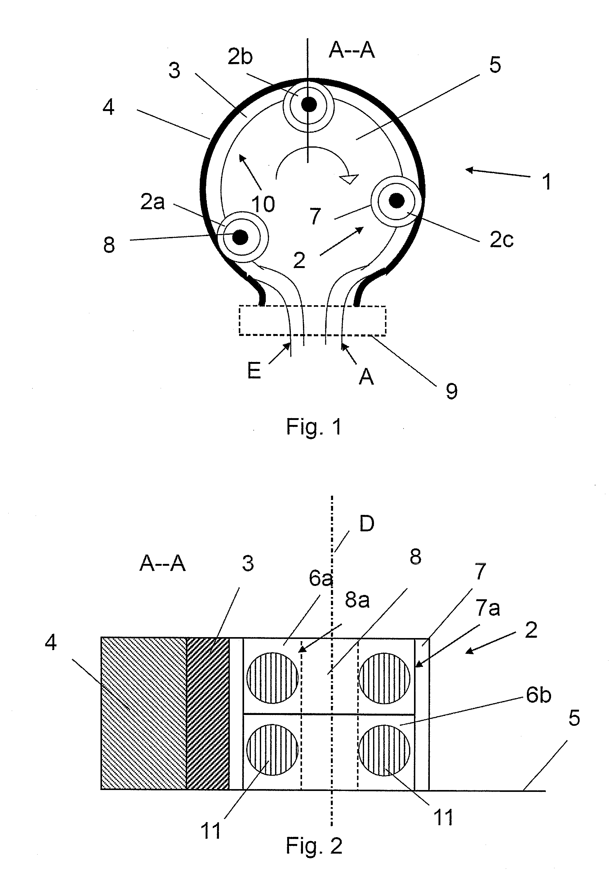
[0009]FIG. 1 shows a peristaltic pump 1 for conveying fluids. The peristaltic pump comprises a stator 4, in which a flexible hose 3 is integrated over a substantially circular path (approximately 360°). As is illustrated in FIG. 1 by the arrow, a rotor 5 is supported in the stator 4. The rotor has radially arranged conveying elements 2a, 2b, 2c. The conveying elements 2a, 2b squeeze the hose 3 in the section 10. A motor, not illustrated in greater detail, cooperates with the rotor 5 and, in particular, moves the squeezed fluid section 10 progressively in the hose 3 in accordance with the direction of the arrow. The fluid is thus conveyed in the section 10 from the inlet E of the peristaltic pump 1 to the outlet A of the pump 1. Of course, conveyance may also occur in a direction opposite that of the arrow. In this case the peristaltic pump 1 may be used both for pumping and for suction.

[0010]The hose 3 is fixed in a hose clamp 9 in the region of the inlet E and of the outlet A of th...


PUM


Abstract

A peristaltic pump for conveying fluids includes a stator and a rotor supported therein. A flexible hose is integrated in the stator and the rotor includes radially arranged conveying elements which squeeze the hose over a section containing the fluid. The squeezed fluid section moves progressively in the hose under the effect of a motor connected to the rotor. The conveying elements are designed as rotatably mounted rollers that include at least two rolling bearings, of which the outer rings are connected via a common outer sleeve and of which the inner rings are connected to the rotor. Under the effect of the motor, the rotor moves in the stator and the outer rings of the conveying elements roll on the inner surface of the stator.

Description

BACKGROUND AND SUMMARY OF THE INVENTION[0001]The invention relates to a peristaltic pump for conveying fluids, comprising a stator and a rotor supported therein, wherein a flexible hose is integrated in the stator and the rotor comprises radially arranged conveying elements which squeeze the hose over a section containing the fluid, and wherein the squeezed fluid section moves progressively in the hose under the effect of a motor connected to the rotor.[0002]A peristaltic pump is a positive displacement pump in which the medium to be conveyed is pushed through a hose by the external mechanical deformation thereof. German Patent Document DE 10 2008 002 761 A1 discloses an example of such a pump. A drawback of these pumps the high frictional forces occurring between the hose and the conveying elements when the hose is squeezed. As a result of these increased frictional forces, both the transmission driving the rotor of the peristaltic pump and the hose itself are subjected to heavy lo...

Claims


Application Information

Patent Timeline
IPC IPC(8): F04B43/12
CPCF04B43/1261F04B43/1253
Inventor KUSCH, ENGELBERTSCHWARZWAELDER, ACHIMEISENBERG, TILLHIESGEN, NORBERT
Owner ASTRIUM GMBH
Why Eureka
Try Eureka