
Low Force Orthodontic Arch Wire Having Blocks for Improved Treatment

a low-force, treatment technology, applied in the field of arch wires, can solve the problems of increasing overall treatment time, reducing treatment time, and reducing the effectiveness of the typical arch wire to effectively transfer force to the bracket and teeth, and achieve the effect of greater cross-sectional width of the engagement block and better engagemen

Inactive Publication Date: 2012-06-14
ULTRADENT PROD INC
View PDF5 Cites 30 Cited by
  • Summary
  • Abstract
  • Description
  • Claims
  • Application Information

AI Technical Summary

Benefits of technology

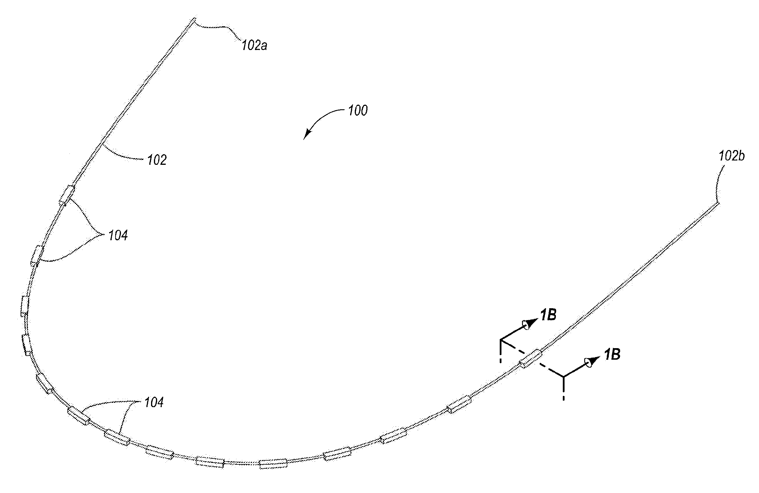
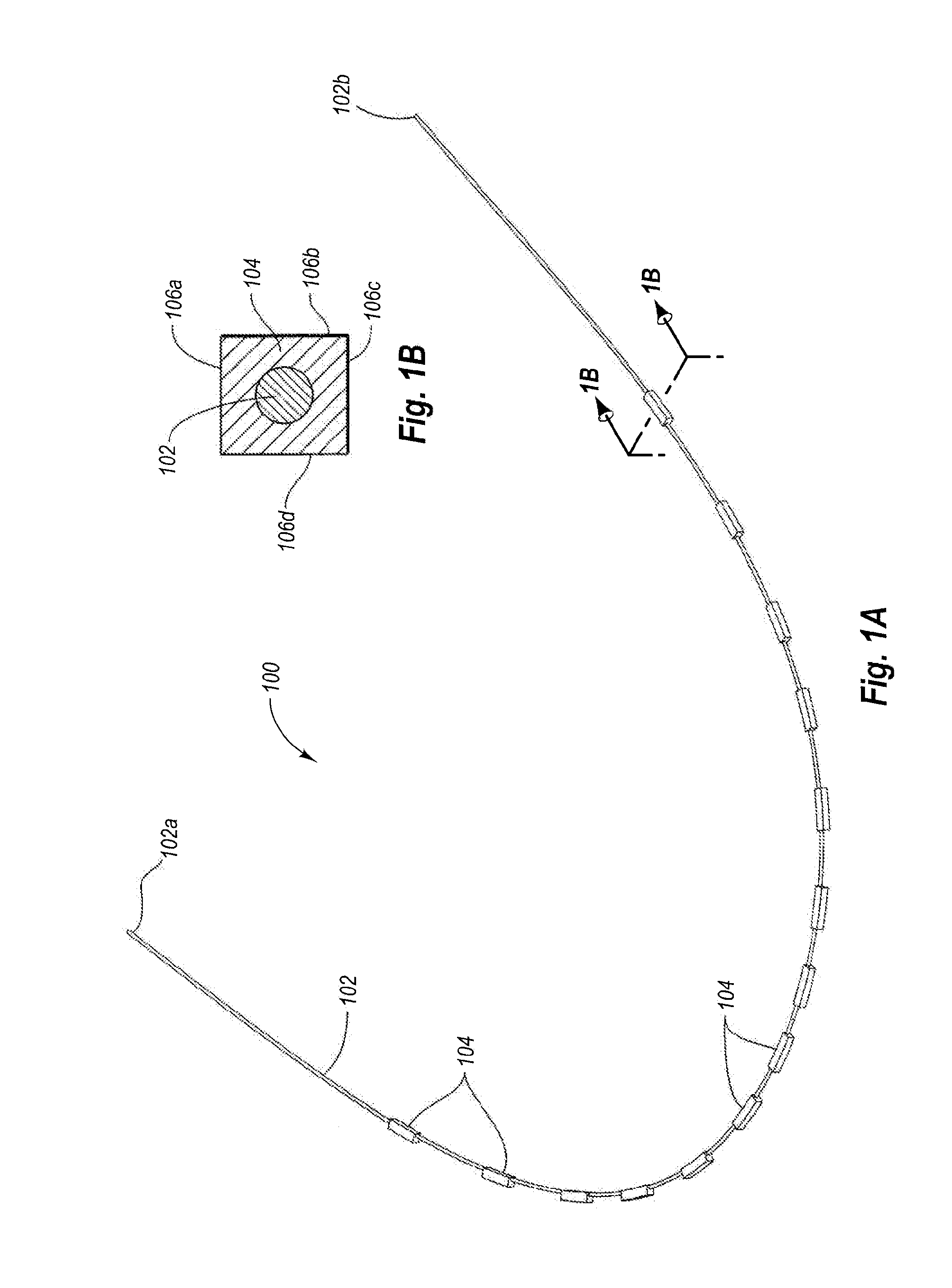
[0013]The present invention is directed to low force orthodontic arch wires capable of applying torquing and / or other corrective forces early in orthodontic treatment. The low force arch wire includes a core wire formed of a material having shape memory that extends along a generally curved arch wire axis between a first end and a second end. The arch wire further includes a plurality of bracket engagement blocks disposed in spaced apart relationship along the length of the core wire. Each engagement block is configured for placement within the slot of a corresponding orthodontic bracket with which it works to move the teeth in a desired direction. The engagement blocks are advantageously enlarged relative to the core wire (i.e., the cross-sectional width of the engagement blocks is greater than the cross-sectional width of the core wire), providing for better engagement between any given engagement block and its corresponding bracket slot as compared to if the engagement blocks were not present.
[0014]In short, the enlarged engagement blocks provide for increased surface contact and engagement between the slot and arch wire than would otherwise occur if the blocks were absent. This improved engagement and reduced play of the arch wire in the bracket slot results in better application of corrective forces over a longer period of time. For example, a typical patient may visit the orthodontic practitioner about once every 6 weeks to have adjustments in the arch wire and / or brackets made. Application of corrective forces is best just after the adjustments are made. Because of play between the arch wire and bracket slot, a typical arch wire loses its ability to effectively transfer forces to the bracket and teeth as the teeth begin to move. Another adjustment is necessary. Typically, the vast majority of corrective movement occurs for only about 2 weeks after adjustment. After this point, because of play between the arch wire and bracket slots, little movement occurs. This period of time, which may be as much as about 4 weeks of a 6 week adjustment interval, is mostly wasted. Corrective movement that lasts longer than this typical 2 weeks is possible by using a larger, stiffer arch wire (which reduces play between the bracket slot and arch wire), but this is uncomfortable for the patient, and may also actually increase overall treatment time as recent studies have shown that consistent low force application actually moves the teeth faster than high forces from stiffer arch wires.
[0015]In contrast, the thin core wire portions of the arch wire advantageously result in an arch wire with relatively low stiffness, so that the arch wire applies low corrective forces to the brackets and teeth. These characteristic low forces result in decreased treatment time, as the teeth tend to move faster under application of such forces. This unique combination of low stiffness coupled with the enlarged engagement blocks allows for corrective forces to be relatively small, comfortable, and more efficient, providing excellent engagement (i.e., reduced play) between the arch wire and the bracket slots. This combination of better engagement, reduced play, and continuous low force advantageously allows for significant reduction in treatment times.
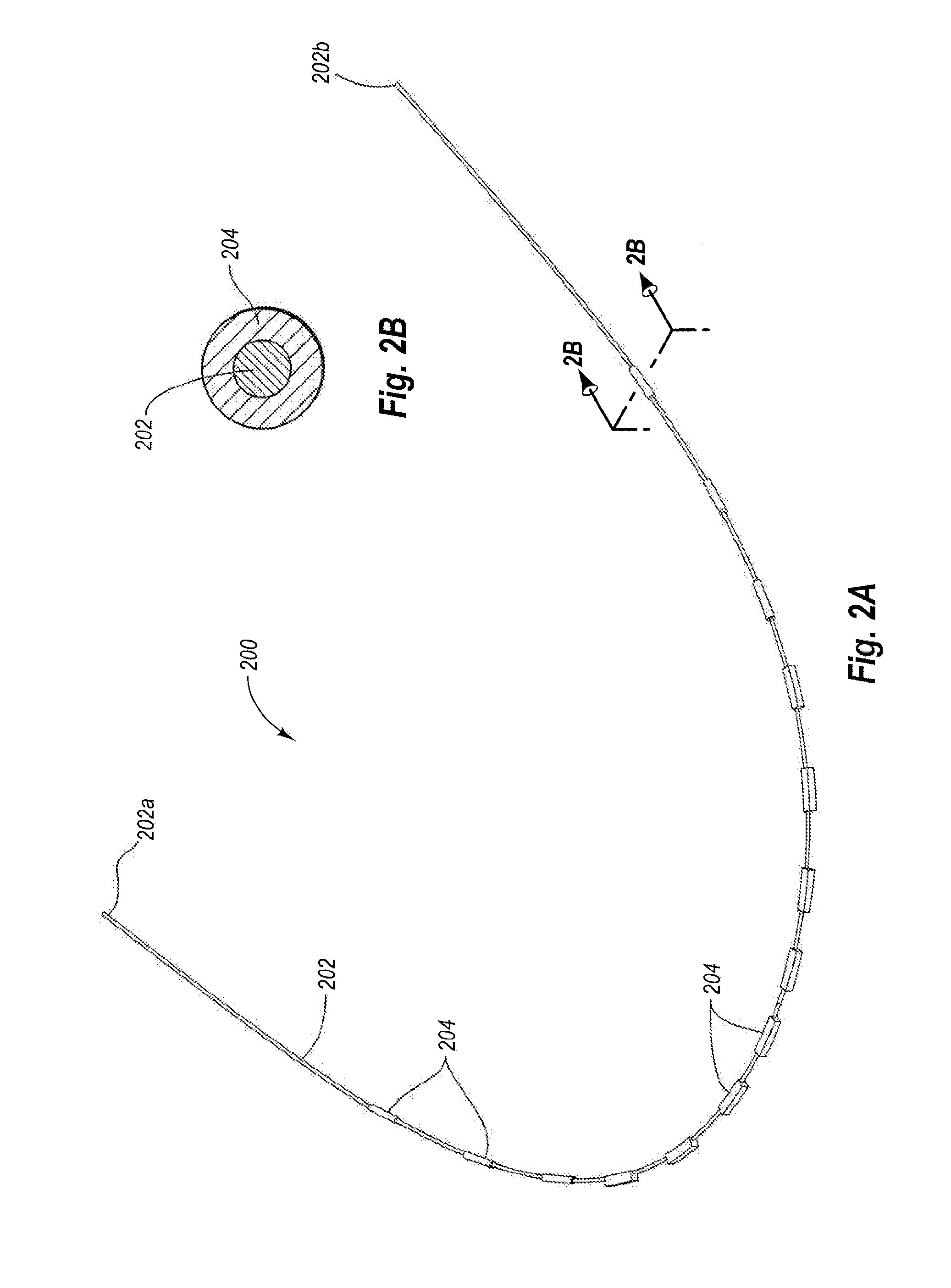
[0016]According to one embodiment, at least some of the engagement blocks will have a rectangular (e.g., square) cross-section. Some of the engagement blocks (e.g., corresponding to the rearward oriented teeth) can have a round (e.g., circular) cross-section. Rounded blocks do not provide a torque value but facilitate lateral of the bracket relative to the block owing to reduced friction between rounded engagement blocks and brackets compared to rectangular blocks.
[0018]In some embodiments, the orthodontic arch wires may advantageously include built-in prescription features for providing corrective movements to misaligned teeth. In particular, the arch wire may include built-in prescription features for providing a predetermined or desired level of corrective torque, angulation, and / or rotational movement to a patient's teeth. The built-in prescription can be provided by angling some or all of engagement blocks relative to the axis of the arch wire and / or relative to each other. When the wire and engagement blocks are coupled with the brackets, the orthodontic arch wire assembly is able to move the patient's teeth in a desired way to correct misalignment of the teeth.

Problems solved by technology

Because of play between the arch wire and bracket slot, a typical arch wire loses its ability to effectively transfer forces to the bracket and teeth as the teeth begin to move.
Corrective movement that lasts longer than this typical 2 weeks is possible by using a larger, stiffer arch wire (which reduces play between the bracket slot and arch wire), but this is uncomfortable for the patient, and may also actually increase overall treatment time as recent studies have shown that consistent low force application actually moves the teeth faster than high forces from stiffer arch wires.
These characteristic low forces result in decreased treatment time, as the teeth tend to move faster under application of such forces.
Rounded blocks do not provide a torque value but facilitate lateral of the bracket relative to the block owing to reduced friction between rounded engagement blocks and brackets compared to rectangular blocks.

Method used


Image

  • Low Force Orthodontic Arch Wire Having Blocks for Improved Treatment
  • Low Force Orthodontic Arch Wire Having Blocks for Improved Treatment
  • Low Force Orthodontic Arch Wire Having Blocks for Improved Treatment

Examples


example 1

[0099]MBT Prescription

MBTToothtorqueangulationrotationUpperscentral 22°4°(Mandibular)lateral 10°8°cuspid 0°8°1st and 2nd bicuspids −7°0°1st molar−14°—10° 2nd molar−19°—8°partially erupted 2nd molar−14°—10° Lowersanteriors −6°0°(Maxillary)cuspids 0°3°1st bicuspid−12°2°2nd bicuspid−17°2°1st molar−20°—0°2nd molar−20°—0°partially erupted 2nd molar−10°—0°

example 2

[0100]Roth Prescription

RothToothtorqueangulationrotationUpperscentral14°5°(Mandibular)lateral 7°8°cuspid−3°10° 1st and 2nd bicuspids−7°0°1st molarTBD—TBD2nd molarTBD—TBDpartially erupted 2nd molarTBD—TBDLowersanteriors−1°0°(Maxillary)cuspids−7°6°1st bicuspid−17° 0°2nd bicuspid−22° 0°1st molarTBD—TBD2nd molarTBD—TBDpartially erupted 2nd molarTBD—TBD

example 3

[0101]Bioprogressive Prescription

Bioprogressive (Hilgers)ToothtorqueangulationrotationUpperscentral22°5°(Mandibular)lateral14°8°cuspid 7°10° 1st and 2nd bicuspids−7°0°1st molarTBD—TBD2nd molarTBD—TBDpartially erupted 2nd molarTBD—TBDLowersanteriors−1°0°(Maxillary)cuspids 7°5°1st bicuspid−11° 0°2nd bicuspid−17° 0°1st molarTBD—TBD2nd molarTBD—TBDpartially erupted 2nd molarTBD—TBD

[0102]While the foregoing prescriptions may be similar to those found in bracket sets that have angled arch wire slots, it should be understood that the direction in which the engagement blocks are rotated or angled matches the desired movement of the teeth. By contrast, the angled slots in prescription brackets are angled in a direction that is opposite to the desired movement. In this way, the inventive orthodontic arch wires provide a more intuitive and meaningful prescription as compared to prescription brackets. In addition, they can be used with generic brackets that do not require intricate positioning ...


PUM

PropertyMeasurementUnit
Angleaaaaaaaaaa
Angleaaaaaaaaaa
Angleaaaaaaaaaa

Abstract

Low force orthodontic arch wires (100) include a core wire (102) formed of a material having shape memory that extends along a generally curved arch wire axis between a first end (102a) and a second end (102b). The arch wire (100) further includes a plurality of bracket engagement blocks (104) disposed in spaced apart relationship along the length of the core wire (102). Each engagement block (104) is configured for placement within the slot of a corresponding orthodontic bracket with which it works to move the teeth in a desired direction. The engagement blocks (104) are advantageously enlarged relative to the core wire (102), providing for better engagement and reduced play between any given engagement block (104) and its corresponding bracket slot as compared to if the engagement blocks (104) were not present. The engagement blocks (104) may be disposed relative to the core wire (102).

Description

BACKGROUND OF THE INVENTION[0001]1. The Field of the Invention[0002]The present invention relates to arch wires for use with orthodontic brackets in correcting spacing and orientation of the teeth.[0003]2. The Relevant Technology[0004]Orthodontics is a specialized field of dentistry that involves the application of mechanical forces to urge poorly positioned or crooked teeth into correct alignment and orientation. Orthodontic procedures can be used for cosmetic enhancement of teeth, as well as medically necessary movement of teeth to correct overjets and / or overbites. For example, orthodontic treatment can improve the patient's occlusion, or enhanced spatial matching of corresponding teeth.[0005]The most common form of orthodontic treatment involves the use of orthodontic brackets and wires, which together are commonly referred to as “braces.” Orthodontic brackets are small slotted bodies configured for direct attachment to the patient's teeth or, alternatively, for attachment to ba...

Claims


Application Information

Patent Timeline
IPC IPC(8): A61C7/28B23P11/00
CPCA61C7/12Y10T29/49826A61C7/20
Inventor LEWIS, PAUL E.
Owner ULTRADENT PROD INC
Learn More