
Universal Frame For Flat Panel Displays

Inactive Publication Date: 2012-06-07
KUSN YIFENG SHEET METAL TECH
View PDF25 Cites 23 Cited by
  • Summary
  • Abstract
  • Description
  • Claims
  • Application Information

AI Technical Summary

Benefits of technology

[0005]A main object of the present invention is to provide a universal flat panel display frame which can adjust and fix the flat panel display at desired position and desired angle conveniently.
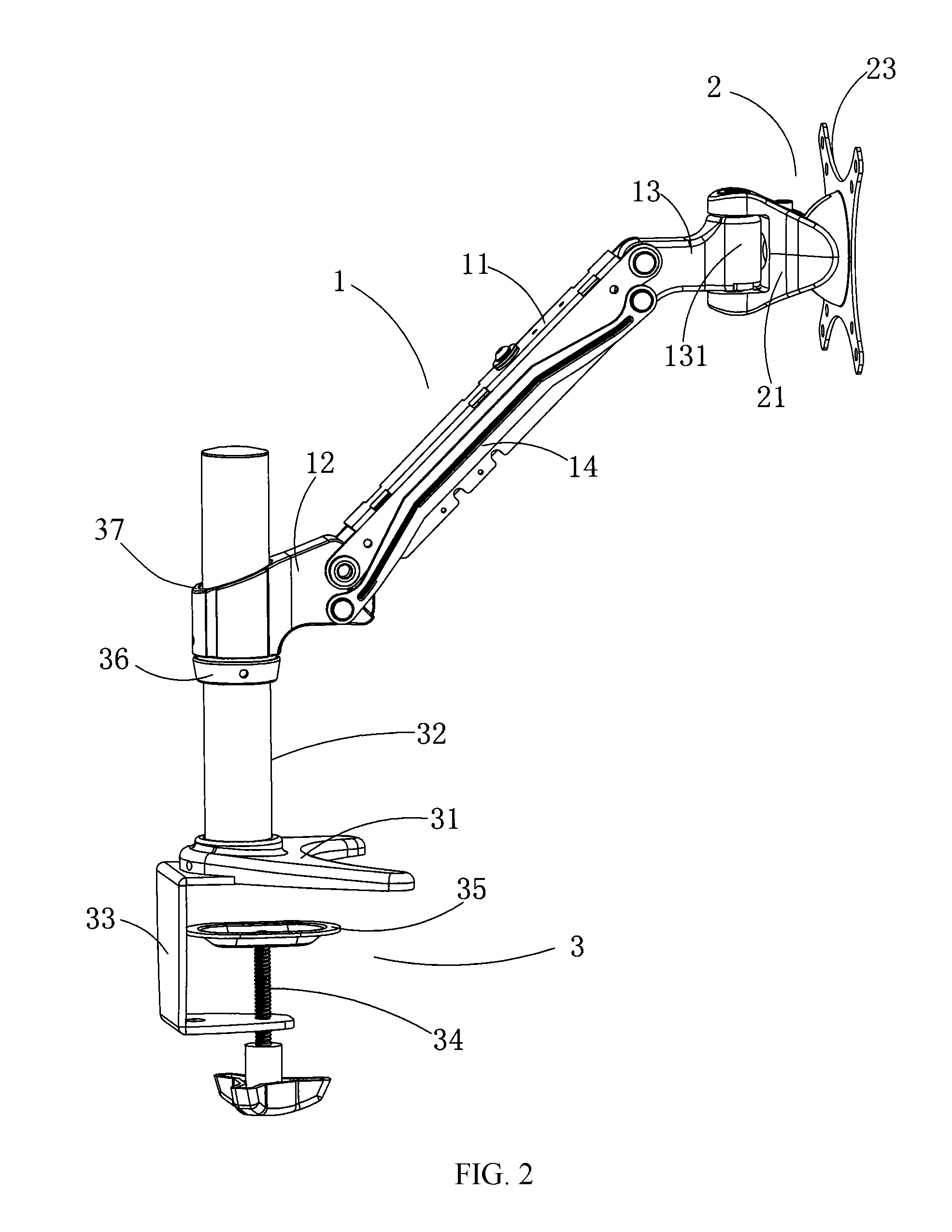
[0011]Furthermore, the supporting arm system comprises two locating loops respectively sleeved on two connecting points between the supporting base and the connecting bars for forming a lock mechanism, wherein when the linkage mechanism passes its dead-point position, one side of the supporting arm is blocked by the locating loops so as to avoid the flat panel display is elevated by the excessive elastic force of the spring 15. Concretely speaking, when the supporting arm is moved slightly down after the linkage mechanism reaching its dead-point position, the linkage mechanism will pass its dead-point position, then the side of the supporting arm is blocked by the locating loops for avoiding further falling, that is, the supporting arm is locked.
[0012]Furthermore, taking the using direction of the flat panel display as reference, the supporting arm system further comprises an adjustable spring base, which comprises two wedge blocks provided at the front portion of the supporting arm; and an adjustable bolt, wherein two wedge blocks have two slop fitting with each other respectively, and the adjustable bolt is adjustably screwed into the two wedge blocks, while the fixed end of the spring is fixed on the adjustable spring base. A main purpose of the adjustable spring base is to make the flat panel display move smart. With adjustment of an assembly length of two wedge blocks by adjusting the adjustable bolt, it could adjust the pretightening force of the spring to meet various flat panel displays with different weights.
[0013]Furthermore, taking the using direction of the flat panel display as reference, the supporting arm system further comprises a wiring cover which is fixedly covered outside the supporting arm system, wherein the wiring cover has a plurality of wiring ducts for locating wires therein. Therefore, the power wire and the signal wire of the flat panel display are respectively located in the wiring ducts so as to avoid damage when the flat panel display changing its angle with the desktop, at the same time, to make a more beautiful appearance of the present invention.
[0015]Furthermore, taking the using direction of the flat panel display as reference, the universal head has a spherical concave provided at the front portion thereof, wherein the spherical concave has a square hole positioned in the center thereof communicating the front portion with the rear portion of the universal head. Correspondingly, the connecting plate has a spherical convex provided at the middle portion thereof matching with the spherical concave of the universal head; and a center hole provided in the center of the spherical convex. The universal head system 2 comprises a square-rod fastening bolt having a capped end, a square-rod middle portion, and a threaded end; and a fastening nut matching with the square-rod fastening bolt, wherein the square middle portion is matched with the square hole of the spherical concave. The threaded end of the square-rod fastening bolt is passed through the center hole of the connecting plate and the square hole of the universal head from front to back, and engaged with the fastening nut, wherein the square-rod middle portion of the square-rod fastening bolt is located within the center hole of the connecting plate and the square hole of the universal head, and the capped end of the square-rod fastening bolt is blocked by an rear portion of the connecting plate. The connecting plate comprises a plurality of spherical friction linings respectively provided between the connecting plate and the universal head, and the connecting plate and the capped end of the square-rod fastening bolt, wherein each spherical friction lining has a square frictional hole in the center thereof matching with the square-rod middle portion of the square-rod fastening bolt. The connection structure between the universal head and the connecting plate as recited above allows the flat panel display installed thereon, according to different needs, to adjust its elevation angle and left / right angle, even its vertical angle, that is, a satisfactory friction force can be obtained by adjusting a fastening moment of the square-rod fastening bolt. Owing to fixed by the square hole of the universal head, the square fastening bolt itself does not rotate with the motion of the universal head. Therefore, the friction remains constant for a long enough time so as to make the usage of the flat panel display conveniently.

Problems solved by technology

Therefore, the weakness of the fixed pedestal is also obvious.
Secondly, the flat panel display installed on the fixed pedestal is not easy to be moved, that is, it is hard to adjust its incline angle or to rotate the flat panel display at a larger angle for showing its screen to other people.
Thus, the fixed pedestal is not convenient for the flat panel display to adjust its position.

Method used


Image

  • Universal Frame For Flat Panel Displays
  • Universal Frame For Flat Panel Displays
  • Universal Frame For Flat Panel Displays

Examples


Embodiment Construction

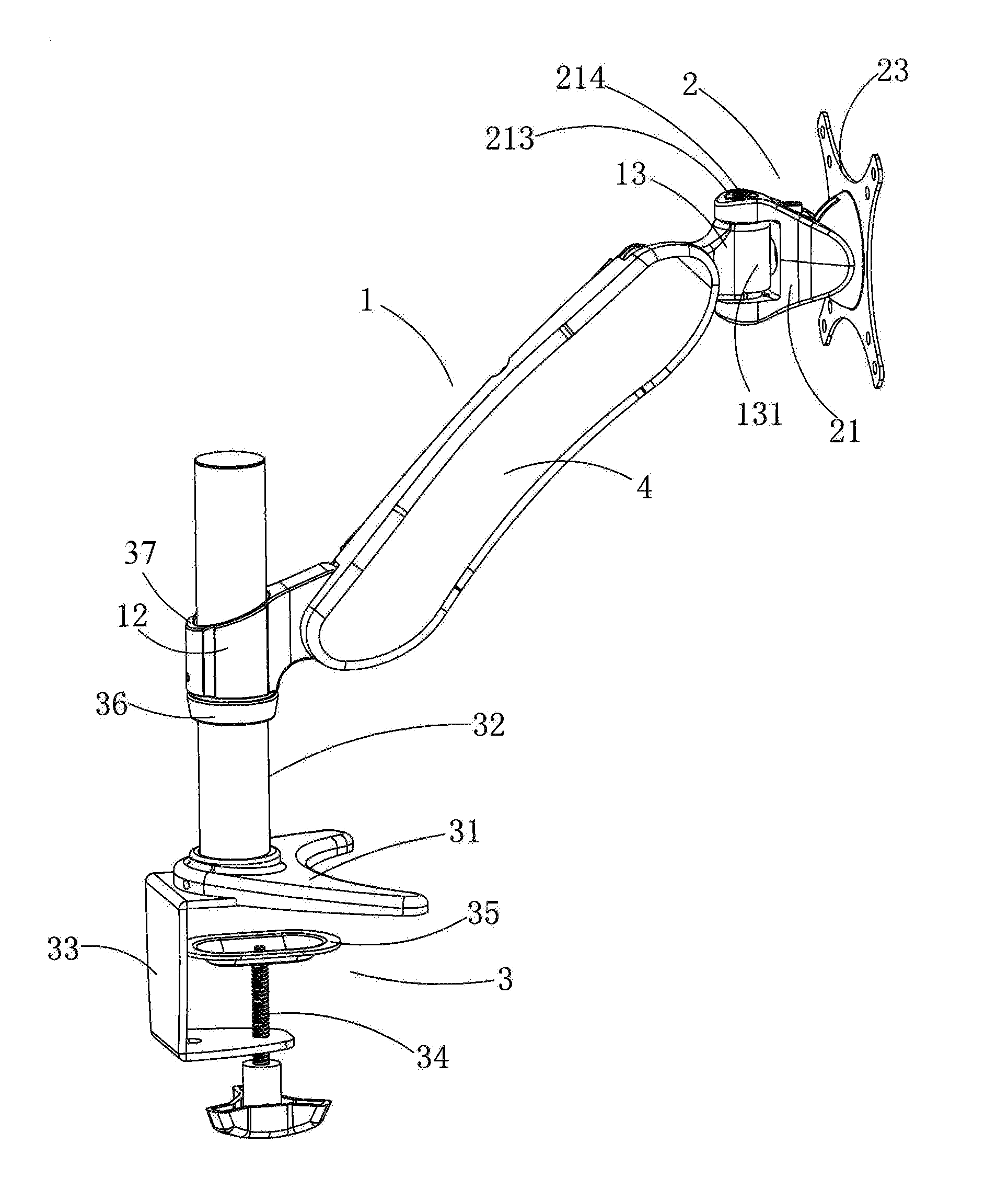
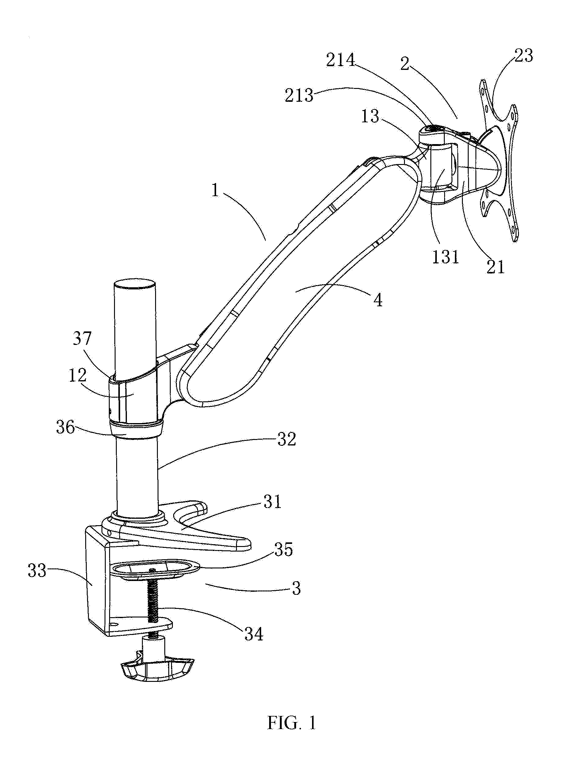
[0027]Referring to FIG. 1-FIG. 6 of the drawings, a universal flat panel display frame according to a preferred embodiment of the present invention is illustrated, wherein the universal flat panel display frame comprises a supporting arm system 1, a universal head system 2 and a fixing pedestal system 3. Taking the using direction of the flat panel display as reference, the fixing pedestal system 3 comprises a supporter 31, a column 32, a U-plate 33, a tightening bolt 34, a tightening cover 35, a locating sleeve 36 and a rotating tapered sleeve, wherein the column 32 is fixed on the supporter 31, the U-plate 33 clamps an edge of an desktop, and the supporter 31 is fixed on the U-plate 33. The U-plate 33 has an internal thread hole provided in a bottom thereof, having threads engaged with threads of the tightening bolt 34. A top threaded end of the tightening bolt 34 is screwed through the internal thread hole which provided in the bottom of the U-plate 33, and the tightening cover 3...


PUM


Abstract

The present invention provides a universal flat panel display frame which includes a supporting arm system, a universal head system and a fixing pedestal system. The universal flat panel display frame applies a translation mechanism with dual connecting rod supported by a spring force, and a crosshead universal head system, so as to allow the flat panel display installed thereon to be adjusted and fixed at a desired position and a desired angle at will. Only one person could activate the flat panel display by hand, and the height, front / back incline angle and right / left incline angle of the flat panel display can be adjusted at random just by applying a little force. Therefore, the present invention is convenient for a user to adjust the flat panel display at a desired position, or to rotate the flat panel display at a desired angle to show the screen to other people.

Description

BACKGROUND OF THE PRESENT INVENTION [0001]1. Field of Invention[0002]The present invention relates to a frame for flat panel displays, and more particularly to a frame which allows the flat panel display installed thereon to adjust its incline angle and distance to a user at random.[0003]2. Description of Related Arts[0004]At present, the flat panel display has been widely using as computer display device due to its light weight, thin screen and beautiful appearance. Generally, the flat panel display is installed on a fixed pedestal which is directly sit on desktop and allows the flat panel display to adjust its frontal incline angle. Therefore, the weakness of the fixed pedestal is also obvious. At first, the fixed pedestal has occupied valuable area of the desktop. Secondly, the flat panel display installed on the fixed pedestal is not easy to be moved, that is, it is hard to adjust its incline angle or to rotate the flat panel display at a larger angle for showing its screen to o...

Claims


Application Information

Patent Timeline
IPC IPC(8): H05K7/00F16L3/08
CPCF16M11/04F16M11/10F16M11/2014F16M11/2092F16M2200/063F16M13/02F16M13/022F16M2200/044F16M11/24
Inventor LIM, SEONG WONG
Owner KUSN YIFENG SHEET METAL TECH
Learn More