
Control system having tool tracking

Active Publication Date: 2012-05-31
CATERPILLAR INC
View PDF14 Cites 28 Cited by
  • Summary
  • Abstract
  • Description
  • Claims
  • Application Information

AI Technical Summary

Benefits of technology

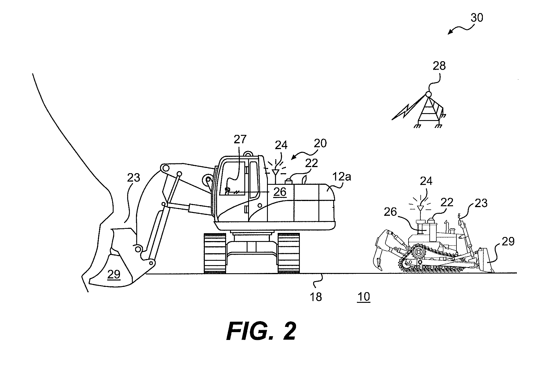
[0007]In one aspect, the present disclosure is directed to a control system for use with a machine having a work tool and operating at a work site. The control system may include a sensor associated with the work tool and configured to generate a signal indicative of a position of the work tool, an offboard worksite controller, and an onboard controller in communication with the sensor and the offboard worksite controller. The onboard controller may be configured to receive from an operator an input indicative of a current task being performed by the machine, and track movement of a portion of the work tool corresponding with the operat

Problems solved by technology

Operation of the machine itself, however, can cause changes in the terrain that make control difficult.
Unfortunately, such surveys and updates can interrupt the excavation process and result in decreased productivity and efficiency.
Although the system of the '563 patent may provide real time knowledge of the terrain over which the autonomous mining machine operates, it may be less than optimal.
For example, the three-dimensional implement position may generate large amounts of data that can be cumbersome to process, slows down the system, and requires a large storage space.

Method used


Image

  • Control system having tool tracking
  • Control system having tool tracking
  • Control system having tool tracking

Examples


Embodiment Construction

[0014]FIG. 1 illustrates an exemplary worksite 10 having multiple, simultaneously-operable machines 12 performing a variety of predetermined tasks. Worksite 10 may include, for example, a mine site, a landfill, a quarry, a construction site, or any other type of worksite known in the art. The predetermined tasks may be associated with altering the current geography at worksite 10 and include a clearing operation, a leveling operation, a hauling operation, a digging operation, a loading operation, or any other type of operation that functions to alter the current geography at worksite 10.

[0015]Worksite 10 may include multiple locations designated for particular purposes. For example, a first location 14 may be designated as a load location at which a mobile loading machine 12a operates to excavate and fill multiple mobile haul machines 12b with material. A second location 16 may be designated as a dump location at which machines 12b discard their payloads. Machines 12b may follow a t...


PUM

PropertyMeasurementUnit
Timeaaaaaaaaaa
Volumeaaaaaaaaaa
Distanceaaaaaaaaaa

Abstract

A control system is disclosed for use with a machine having a work tool and operating at a work site. The control system may have a sensor associated with the work tool and configured to generate a signal indicative of a position of the work tool, an offboard worksite controller, and an onboard controller in communication with the sensor and the offboard worksite controller. The onboard controller may be configured to receive from an operator an input indicative of a current task being performed by the machine, and track movement of a portion of the work tool corresponding with the operator input. The onboard controller may also be configured to communicate the tracked movement to the offboard worksite controller.

Description

RELATED APPLICATIONS[0001]This application is based on and claims the benefit of priority from U.S. Provisional Application No. 61 / 418,344 by Bryan J. EVERETT, Craig L. KOEHRSEN, Rodney R. RICHARDS, and Steven J. COOK, filed Nov. 30, 2010, the contents of which are expressly incorporated herein by reference.TECHNICAL FIELD[0002]The present disclosure relates generally to a machine control system, and more particularly, to a control system for tracking a machine tool.BACKGROUND[0003]Autonomy in excavation applications, for example mining applications, is becoming more common as the drive for productivity, efficiency, and safety increases. In order for an autonomous machine to operate optimally, the machine requires accurate knowledge of the terrain over which the machine operates. Operation of the machine itself, however, can cause changes in the terrain that make control difficult. These terrain changes require that the underlying terrain be continuously surveyed and systems of the ...

Claims


Application Information

Patent Timeline
IPC IPC(8): G06F7/00G05D1/00
CPCE02F9/2045E02F9/265G05D2201/021G05D1/0274G05D2201/0202E21C47/00
Inventor EVERETT, BRYAN J.KOEHRSEN, CRAIG L.RICHARDS, RODNEY R.COOK, STEVEN J.
Owner CATERPILLAR INC
Learn More