
Internal airbag device

a technology of airbags and airbags, which is applied in the direction of pedestrian/occupant safety arrangements, vehicular safety arrangements, vehicle components, etc., can solve the problems of rear seat occupants who do not wear seatbelts being damaged, rear seat occupants b>2/b> to feel discomfort, and the comfort of an occupant sitting in the front seat being greatly restricted, etc., to achieve the effect of absorbing impacts

Inactive Publication Date: 2012-05-31
HYUNDAI MOTOR CO LTD
View PDF12 Cites 101 Cited by
  • Summary
  • Abstract
  • Description
  • Claims
  • Application Information

AI Technical Summary

Benefits of technology

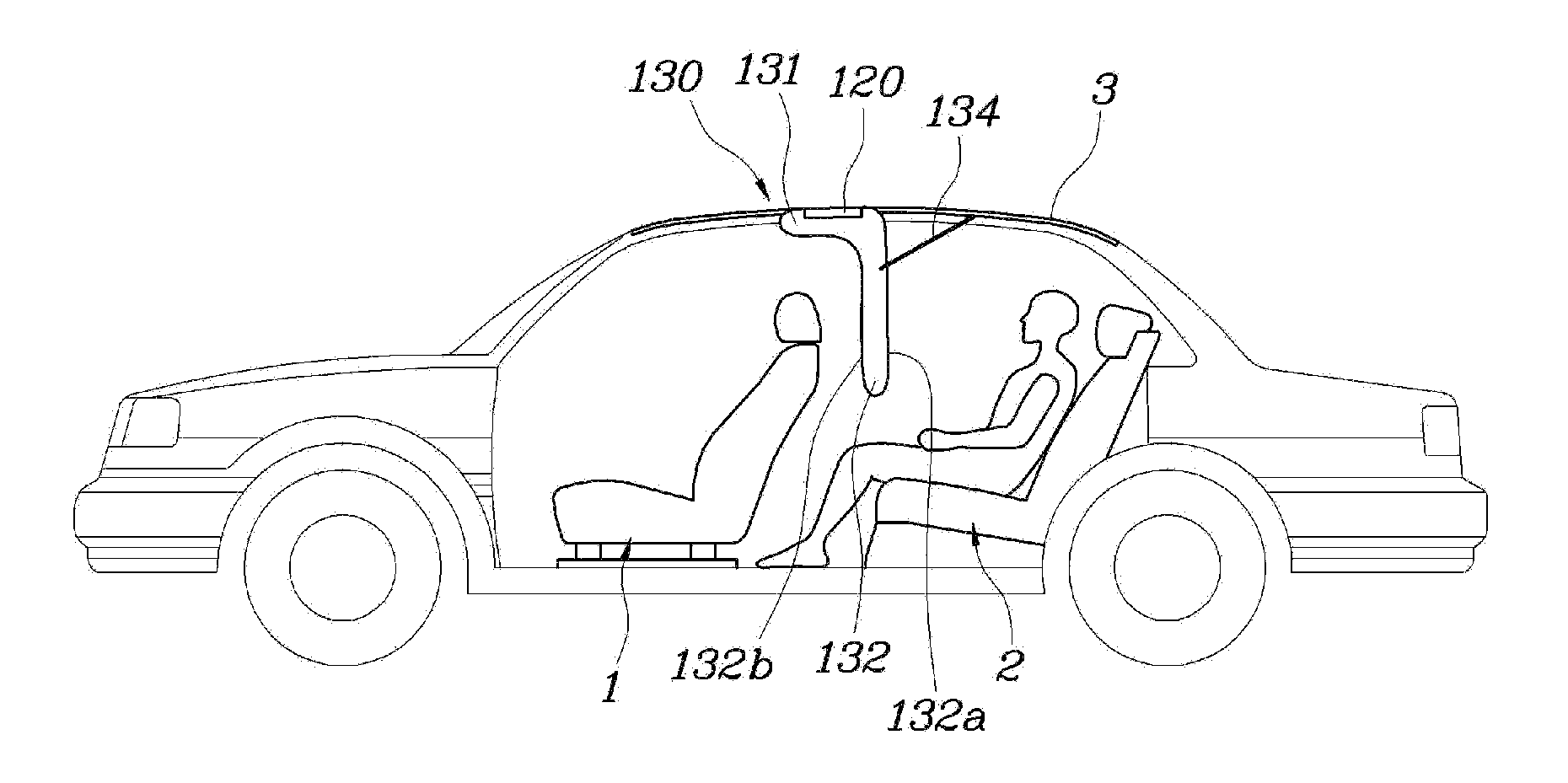
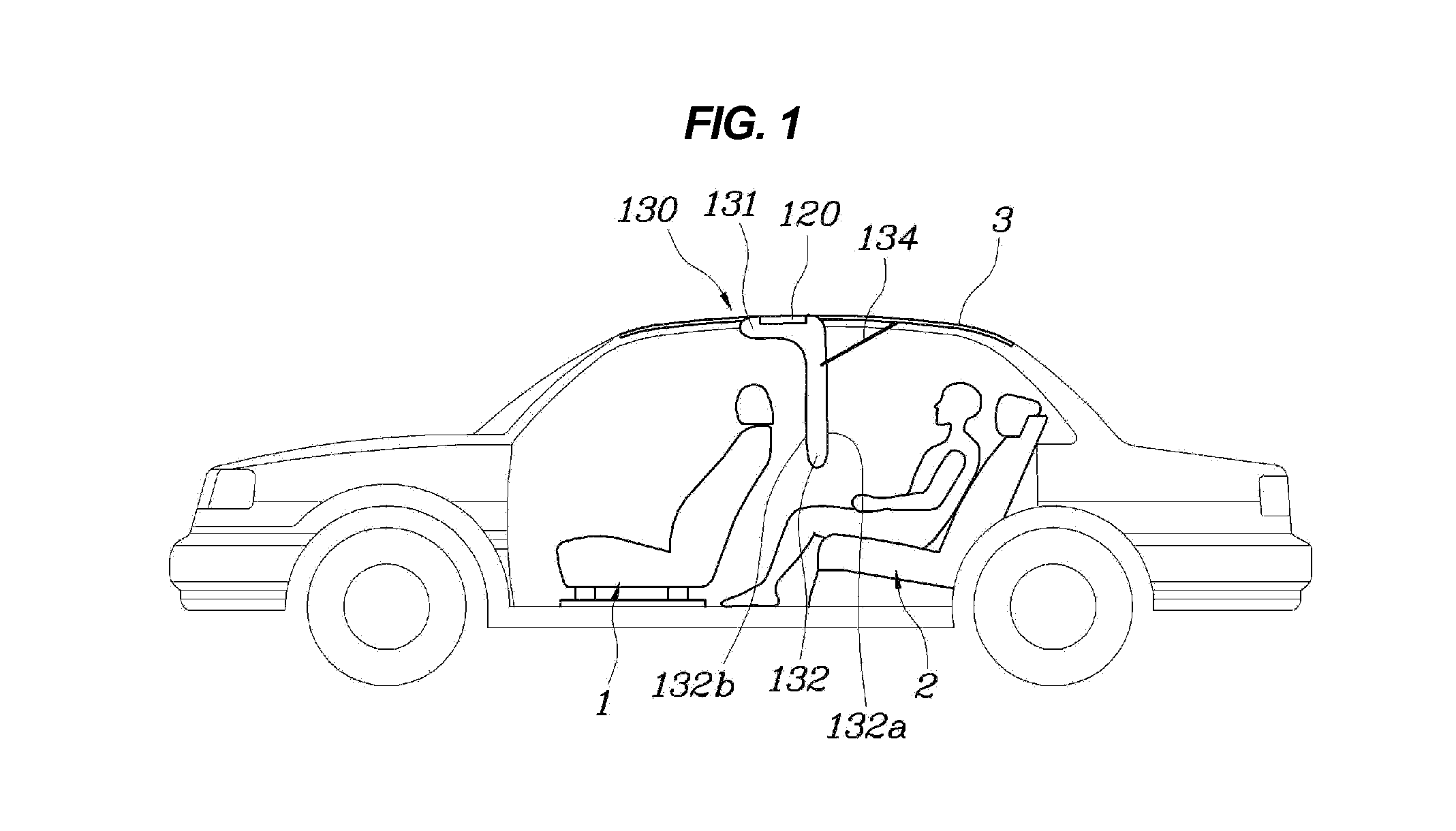
[0011]Various aspects of the present invention are directed to propose an internal airbag device in which an airbag deploys in a vehicle collision between a front seat and a rear seat to prevent a secondary collision of a rear seat occupant with a front seat occupant and with the front seat or frontal objects.
[0014]The vertical airbag section and the roof may be connected by at least a tether in order to reinforce the strength of the deploying airbag.
[0024]According to the present invention as configured as above, during a vehicle collision, the airbag deploys in front of a rear seat occupant between a front seat and a rear seat even when the front seat may be folded forwards, so that the rear seat occupant may be prevented from striking the front seat occupant and the front seat or frontal objects, thereby effectively absorbing impacts applied to the rear seat occupant.

Problems solved by technology

However, rear seat occupants who do not wear a seatbelt may be damaged during a frontal collision of a vehicle by striking the front seat occupants or front seats.
However, such an internal airbag device operates such that an airbag 13, received in an airbag housing 12 mounted in a front seat 11, inflates towards the rear seat occupant's face, causing the rear seat occupant 2 to feel discomfort.
Further, the direction and position of deployment of the airbag vary according to a forward or rearward motion or a reclining angle of a front seat, which is problematic.
However, this is not preferred because the comfort of an occupant sitting in the front seat is also greatly restricted.
Furthermore, conventional airbags which deploy in the vehicle interior during a vehicle collision separately inflate in the side of the front seat and rear seat, respectively, so that they cannot completely protect rear seat occupants from impacts.

Method used


Image

  • Internal airbag device
  • Internal airbag device
  • Internal airbag device

Examples


Embodiment Construction

[0034]Reference will now be made in detail to various embodiments of the present invention(s), examples of which are illustrated in the accompanying drawings and described below. While the invention(s) will be described in conjunction with exemplary embodiments, it will be understood that present description is not intended to limit the invention(s) to those exemplary embodiments. On the contrary, the invention(s) is / are intended to cover not only the exemplary embodiments, but also various alternatives, modifications, equivalents and other embodiments, which may be included within the spirit and scope of the invention as defined by the appended claims.

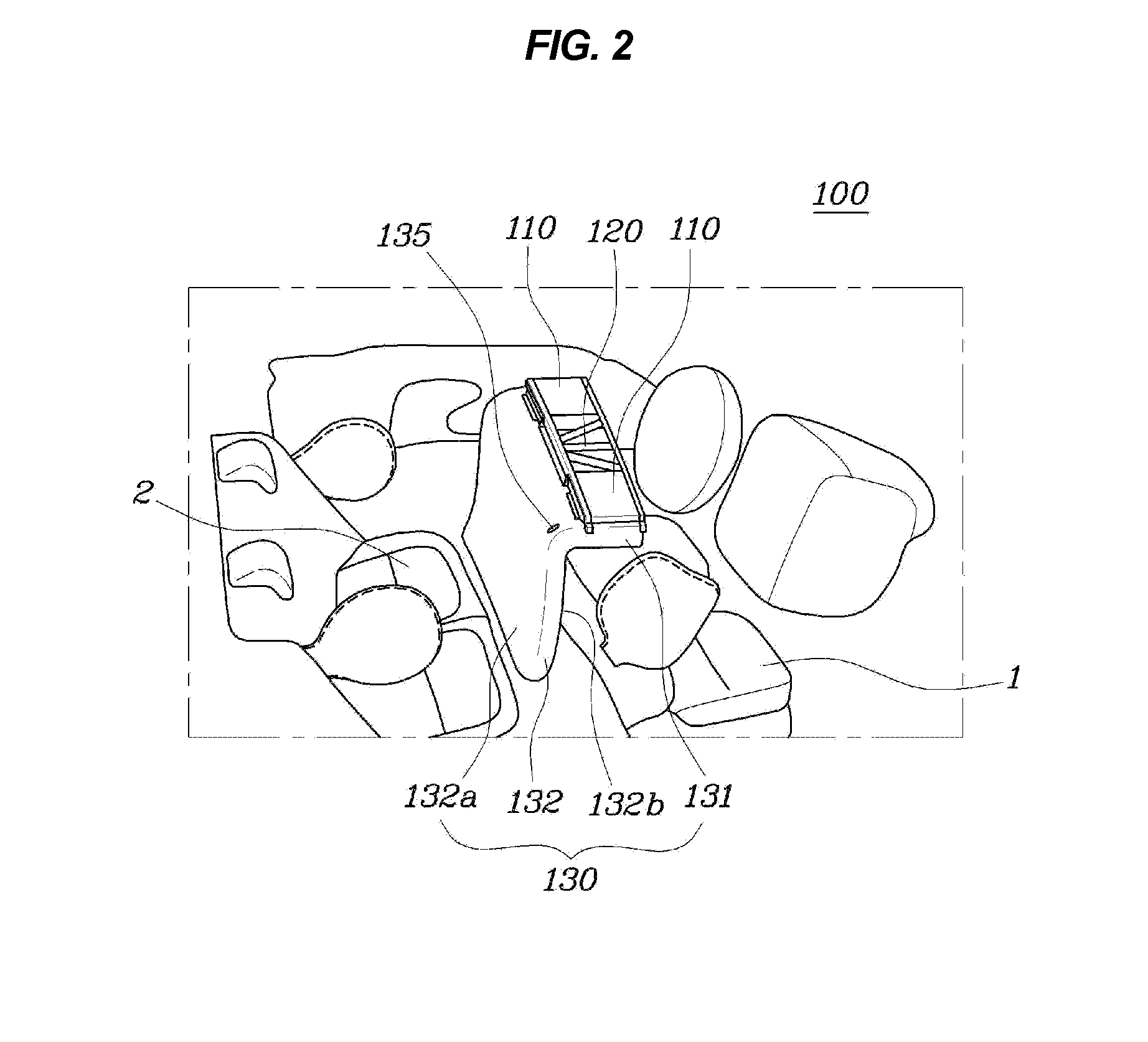
[0035]A first embodiment of an internal airbag device 100, as shown in FIGS. 1 and 2, includes an inflator 110, an airbag housing 120, and an airbag 130 in order to deploy between a front seat and a rear seat to protect rear seat occupants in a safe manner.

[0036]The airbag housing 120 is mounted in a roof 3 in a region between the fro...


PUM


Abstract

An internal airbag device may include an inflator, an airbag housing mounted in a roof in a region between a front seat and a rear seat, and an airbag received in the airbag housing to deploy downwards by gas supplied from the inflator, wherein the airbag includes a horizontal airbag section supported by the roof during the gas may be supplied therein in a deployment thereof, and a vertical airbag section fluid-connected to the horizontal airbag section and extending downwards from an end of the horizontal airbag section opposite the rear seat in a deployment thereof.

Description

CROSS-REFERENCE TO RELATED APPLICATIONS[0001]The present application claims priority to Korean Patent Application No. 10-2010-0119623 filed on Nov. 29, 2010, the entire contents of which is incorporated herein for purposes by this reference.BACKGROUND OF THE INVENTION[0002]1. Field of the Invention[0003]The present invention relates, in general, to an internal airbag device which is mounted in an interior of a vehicle and, more particularly, to an internal air bag device in which an airbag deploys in a vehicle collision between a front seat and a rear seat to prevent a secondary collision of a rear seat occupant with a front seat occupant and with the front seat or frontal objects.[0004]2. Description of Related Art[0005]Generally, vehicles are equipped with a variety of safety devices for protecting a driver and passengers from sudden accidents. Representative safety devices are airbag devices that directly protect a driver and a front seat occupant.[0006]Such airbag devices are in...

Claims


Application Information

Patent Timeline
Patent Type & Authority Applications(United States)
IPC IPC(8): B60R21/16
CPCB60R2021/23386B60R21/214B60R2021/23153B60R21/2338B60R21/239B60R21/231
Inventor CHOI, HYEONG HOCHOI, JUN YEOL
Owner HYUNDAI MOTOR CO LTD
Learn More