
Mist eliminator, moisture removal system, and method of removing water particles from inlet air

a technology of inlet air and eliminator, which is applied in the direction of filtration separation, separation process, transportation and packaging, etc., can solve the problems of substantial problems in gas turbine operation, difficulty in controlling moisture, and difficulty in reducing so as to achieve little or no clogging, no affecting the operation of gas turbines, and no affecting the performance or efficiency of gas turbines

Inactive Publication Date: 2012-05-31
BHA ALTAIR
View PDF6 Cites 22 Cited by
  • Summary
  • Abstract
  • Description
  • Claims
  • Application Information

AI Technical Summary

Benefits of technology

"The present patent provides a mist eliminator and a moisture removal system for a gas turbine. The mist eliminator has a substrate with frusto-conical shaped protrusions that coalesce and retain water particles from moisture-containing air. The system removes fine water particles from the inlet air stream without causing pressure loss or reducing the performance or efficiency of the gas turbine. It is easy to clean and requires little or no maintenance. The technical effects of the patent include coalescing fine water particles into larger droplets, removing fine water particles without causing a pressure loss, and providing a system that requires little or no maintenance and is easy to clean."

Problems solved by technology

Filtering mechanisms serve a primary function to filter solid particulates, but typically fail to control moisture.
Fine moisture droplet contamination is particularly problematic in environments having relatively high humidity, such as in marine or off-shore applications, or in conditions such as rain, mist or fog.
This type of fine moisture droplet migration can cause substantial problems with gas turbine operations.
Generally, heavy rain has drops that are too large to be easily carried in a flow of inlet air.
For example, some filtration systems using filter media experience increased pressure loss across a filter due to the moisture, which results in reduced gas turbine performance during this period of “wet” operation.
Some filter media also retain the moisture which can lead to long periods of time when the pressure loss across the filter is elevated.

Method used


Image

  • Mist eliminator, moisture removal system, and method of removing water particles from inlet air
  • Mist eliminator, moisture removal system, and method of removing water particles from inlet air
  • Mist eliminator, moisture removal system, and method of removing water particles from inlet air

Examples


Embodiment Construction

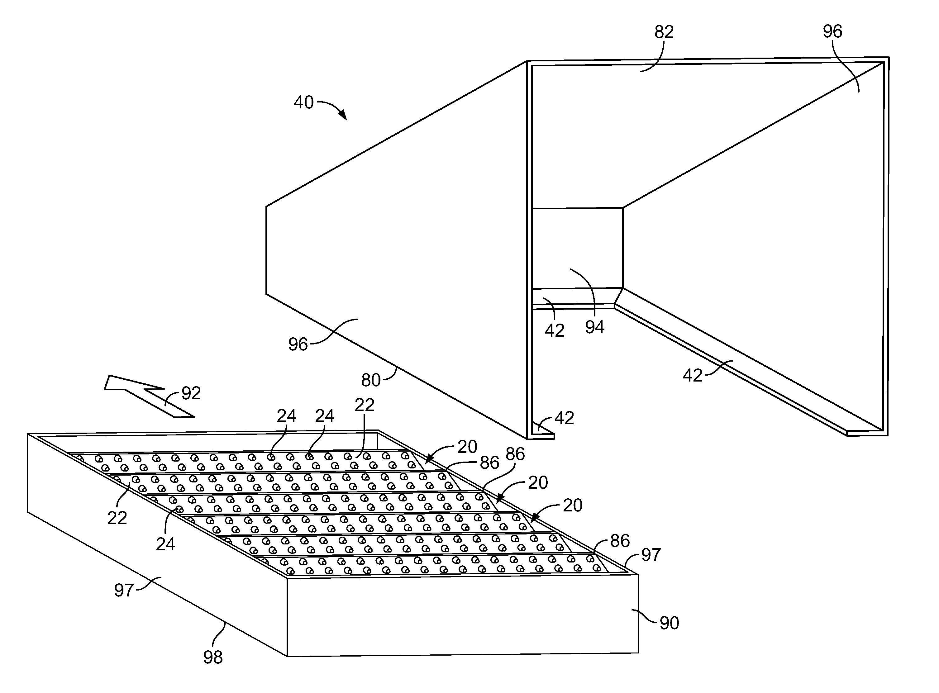
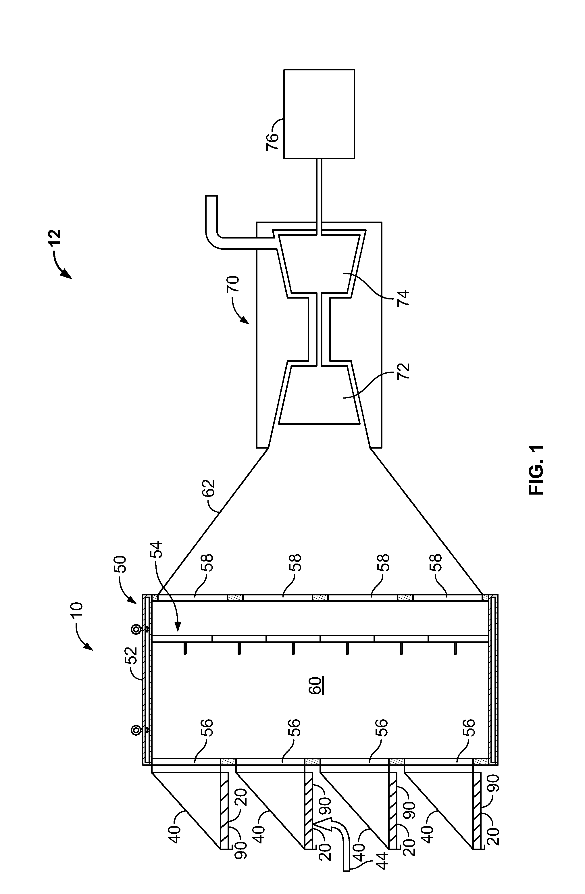
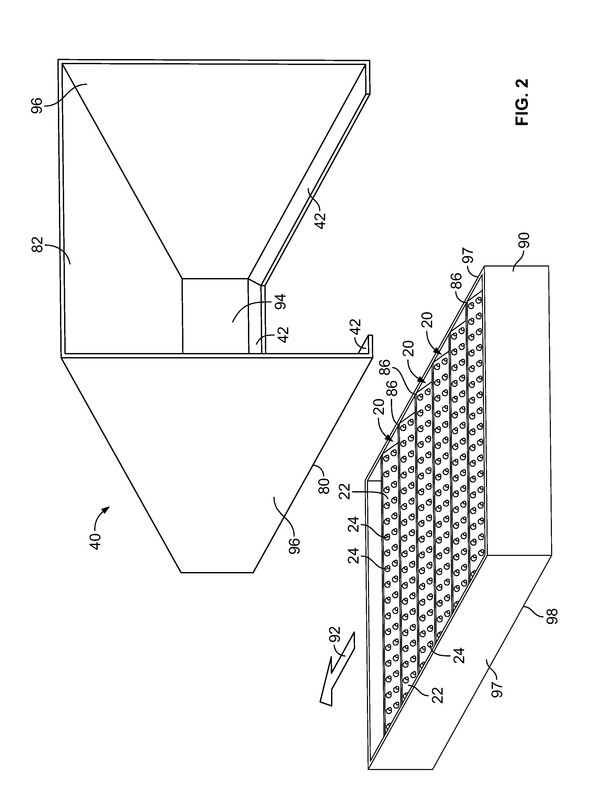
[0028]Provided is a plurality of mist eliminators 20 and a moisture removal system 10 including the plurality of mist eliminators 20 and method for removal of fine water particles 45 from moisture containing inlet air 44. Embodiments of the present disclosure involve a mist eliminator 20 including a substrate 22 having a plurality of frusto-conical shaped protrusions 24 disposed thereon. The plurality of frusto-conical shaped protrusions 24 have a geometry and are positioned at intervals 34 that provide coalescence and retention of water particles or fine water particles 45 from moisture containing air 44 contacting the substrate 22 and frusto-conical shaped protrusions 24.

[0029]FIG. 1 depicts a gas turbine engine 12 including an embodiment of a moisture removal system 10 that eliminates water particles and fine water particles 45 from fog or mist from the inlet air stream 44 to a gas turbine engine 12. By “fine water particles” and its grammatical variations, it is meant that water...


PUM

PropertyMeasurementUnit
heightaaaaaaaaaa
heightaaaaaaaaaa
diameteraaaaaaaaaa

Abstract

A mist eliminator including a substrate and a plurality of frusto-conical shaped protrusions disposed on the substrate is provided. The plurality of frusto-conical shaped protrusions have a geometry and are positioned at intervals that provide coalescence and retention of water particles from moisture containing air contacting the substrate and frusto-conical shaped protrusions. A moisture removal system and a method for removing water particles from inlet air with the mist eliminator are also disclosed.

Description

FIELD OF THE INVENTION[0001]The present disclosure relates generally to a water particle removal system. More specifically, the present disclosure is directed to a mist eliminator, a moisture removal system, and method for removing fine water particles from a gas turbine inlet air stream.BACKGROUND OF THE INVENTION[0002]Some systems for removing moisture from the inlet stream of gas turbines are known. One such known system includes a plurality of filtering mechanisms that filter the inlet air through a plurality of materials and mediums before the inlet air is allowed to proceed to the gas turbine. In one such system, the plurality of filters can include a preliminary filter suspended or attached to the weather hood or hood which is upstream from a primary filter. The filter system is connected by ducting to the gas turbine. The preliminary filters are constructed from filter media that may have hydrophobic properties, for example, a polypropylene fiber material. Filtering mechanis...

Claims


Application Information

Patent Timeline
Patent Type & Authority Applications(United States)
IPC IPC(8): B01D45/08B01D46/42B01D50/00
CPCB01D46/0023B01D2279/60B01D46/10B01D46/003B01D46/62
Inventor JARRIER, ETIENNE RENEDAVIES, JOHNBRYANT, PAUL
Owner BHA ALTAIR
Learn More