
Calibration apparatus, calibration method, and manufacturing method for an electronic device

a manufacturing method and electronic device technology, applied in speed/acceleration/shock measurement, instruments, surveying and navigation, etc., can solve the problems of increasing the production cost increasing the scale of the calibration apparatus, and taking a lot of time and labor to perform the measurement a plurality of times

Active Publication Date: 2012-05-24
SONY COMPUTER ENTERTAINMENT INC
View PDF2 Cites 14 Cited by
  • Summary
  • Abstract
  • Description
  • Claims
  • Application Information

AI Technical Summary

Benefits of technology

The present invention provides a calibration apparatus for a sensor that can cause an electronic device to rotate with each of a plurality of reference axes as a center to detect the rotational speed with each reference axis. The calibration apparatus includes a holder for fixing the electronic device, two motors for causing the holder to rotate at different speeds, and stoppers for restricting the rotational position of the holder. The calibration method involves rotating the electronic device with the first and second motors and acquiring the output value of the sensor while positioning the rotational position of the electronic device in different reference positions. The manufacturing method involves writing calibration data to a nonvolatile memory of the electronic device. The technical effects of the invention include reducing the number of motors needed for calibration, reducing the size of the calibration apparatus, and improving the accuracy of sensor calibration.

Problems solved by technology

However, it takes much time and labor to perform the measurement a plurality of times while the electronic device is thus fixed to the calibration apparatus again and again.
However, such a motor that can realize control of the rotation at the constant rotational speed with high precision tends to be more expensive and larger in scale than the motor that cannot perform such control, and hence providing such a plurality of motors leads to an increase in production cost of the calibration apparatus and an increase in scale of the calibration apparatus.

Method used


Image

  • Calibration apparatus, calibration method, and manufacturing method for an electronic device
  • Calibration apparatus, calibration method, and manufacturing method for an electronic device
  • Calibration apparatus, calibration method, and manufacturing method for an electronic device

Examples


Embodiment Construction

[0035]Hereinafter, an embodiment of the present invention is described in detail with reference to the accompanying drawings.

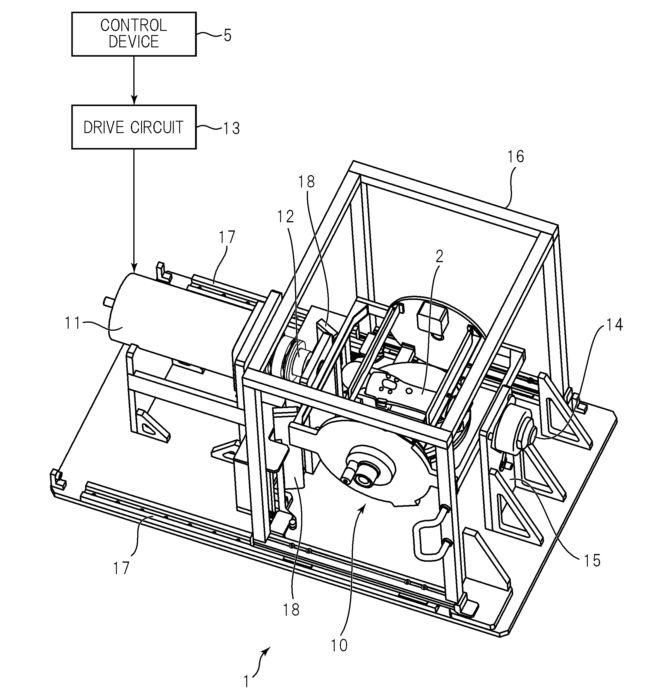
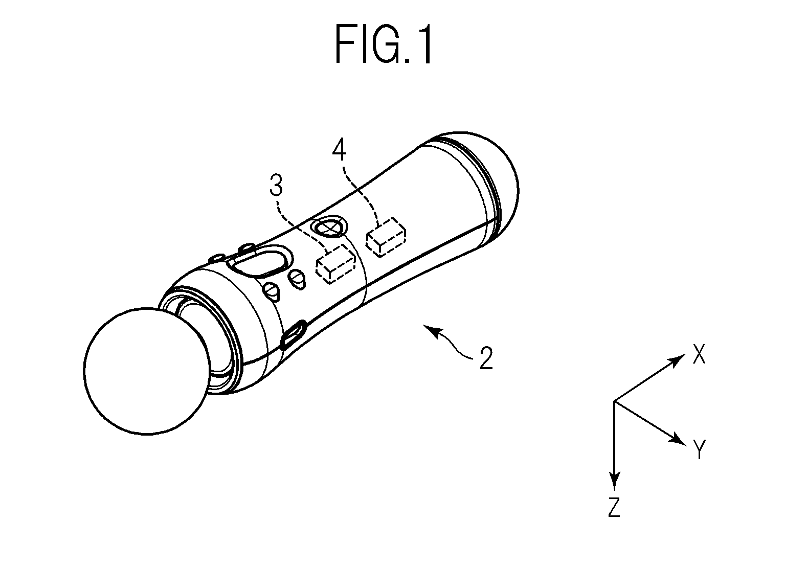
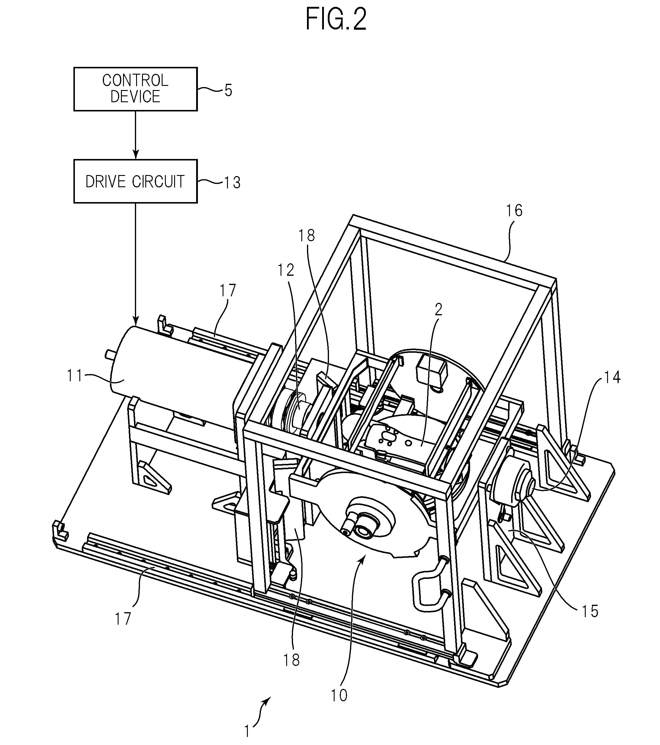
[0036]FIG. 1 is a perspective view illustrating an example of an external appearance of an electronic device 2 to be subjected to a calibration by a calibration apparatus 1 according to the embodiment of the present invention. In this embodiment, the electronic device 2 incorporates a gyroscope 3 and an acceleration sensor 4, and the calibration apparatus 1 acquires sensor output values necessary for calibrations of the gyroscope 3 and the acceleration sensor 4 while changing a posture of the electronic device 2. Here, the electronic device 2 is assumed as a controller of a consumer game machine as an example, but the present invention is not limited thereto, and the electronic device 2 may be any kind of device incorporating a sensor for detecting the posture and movement of the device, such as, for example, a portable game machine or a cellular phone.

[0037]T...


PUM


Abstract

Provided is a calibration apparatus, including: a holder for fixing an electronic device; a first motor for rotating the holder with a first rotation axis as a center; a second motor for rotating the holder with a second rotation axis perpendicular to the first rotation axis as a center; and a stopper for restricting a rotational position of the holder about the second rotation axis to a range between a reference position and a perpendicular position reached by rotating the holder by 90 degrees from the reference position, in which the first motor rotates the holder to which the electronic device is fixed at a predetermined speed in each of states in which the rotational position of the holder about the second rotation axis falls in the reference position and in which the rotational position of the holder about the second rotation axis falls in the perpendicular position.

Description

BACKGROUND OF THE INVENTION[0001]1. Field of the Invention[0002]The present invention relates to a calibration apparatus to be used for a calibration of a sensor for detecting a rotational speed, a calibration method for the sensor, and a manufacturing method for an electronic device which uses the calibration method.[0003]2. Description of the Related Art[0004]There have been proposed various electronic devices, such as a cellular phone and a controller of a consumer game machine, which are provided with a sensor (such as a gyroscope) for detecting a rotational speed. According to such electronic devices, when a user performs an action such as changing an orientation of the electronic device, it is possible to detect the action by using an output from the sensor.[0005]With regard to the sensor, individual sensors have different output characteristics due to individual differences therebetween. Therefore, a calibration for examining the output characteristic of the sensor is perform...

Claims


Application Information

Patent Timeline
Patent Type & Authority Applications(United States)
IPC IPC(8): G01C25/00G06F19/00
CPCG01C25/00G01C19/00G01P21/00
Inventor FUKUSHIMA, NORIYUKIOSAWA, HIROSHI
Owner SONY COMPUTER ENTERTAINMENT INC
Learn More