
Fuel injection control device and method of diesel engine

a technology of fuel injection control and control device, which is applied in the direction of electrical control, process and machine control, etc., can solve the problems of increasing the risk of deterioration of performance such as fuel consumption, affecting the performance of the engine, and increasing the risk of scuffing (seizure or scratching on the cylinder liner surface)

Active Publication Date: 2012-05-24
MITSUBISHI HEAVY IND ENGINE & TURBOCHARGER LTD
View PDF7 Cites 21 Cited by
  • Summary
  • Abstract
  • Description
  • Claims
  • Application Information

AI Technical Summary

Benefits of technology

[0061]According to the present invention, even in a case where a fuel atomization penetration or a combustion flame penetration in a combustion chamber is extended in response to the change of an operation environment condition such as ambient pressure or ambient temperature, or even in a case where an ignition delay is prolonged, the fuel injection timing or the fuel injection pressure can be controlled so that the quantity of the soot adhesion on the cylinder liner surfaces is constrained and the quantity of the contamination of the soot in the lube-oil is constrained.

Problems solved by technology

Hence, because of the divided fuel injections, the control of the fuel injection quantity as well as the fuel injection timing becomes complicated.
Further, Patent Reference 1 does not disclose the control in consideration of the effect of the change of an ambient operation condition such as ambient pressure or ambient temperature as well as the effect of the increase of the soot contact on the cylinder liner surfaces, the increase of the soot being attributable to the fuel atomization penetration or the combustion flame penetration.
Further, as described above, when the contamination of the soot in the lube-oil is increased, the lubricity properties of the lube-oil are deteriorated.
Hence, there has been a problem that the risk of the deterioration of the performance such as fuel consumption as well as the risk of occurrence of scuffing (seizure or scratch on cylinder liner surfaces) may increase.
Hereby, however, there has been a problem that

Method used


Image

  • Fuel injection control device and method of diesel engine
  • Fuel injection control device and method of diesel engine
  • Fuel injection control device and method of diesel engine

Examples


Embodiment Construction

[0076]Hereafter, the present invention will be described in detail with reference to the modes or embodiments shown in the figures. However, the dimensions, materials, shape, the relative placement and so on of a component described in these modes or embodiments shall not be construed as limiting the scope of the invention thereto, unless especially specific mention is made.

(First Mode)

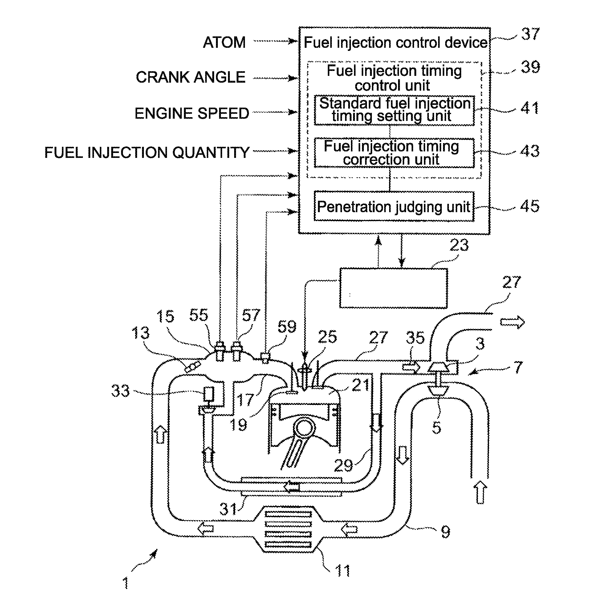
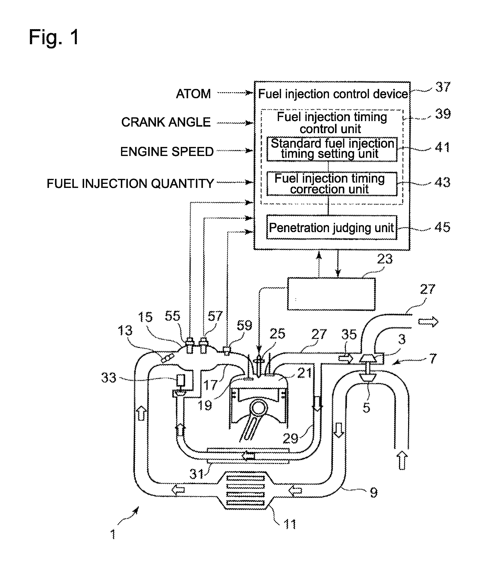
[0077]Based on FIG. 1, a fuel injection control device of a diesel engine according to a first mode of the present invention is now explained.

[0078]As shown in FIG. 1, the diesel engine 1 (hereafter, simply called the engine) is provided with an exhaust turbocharger 7 including, but not limited to, an exhaust turbine 3 and a compressor 5 which is driven by a rotation shaft common to the turbine and the compressor; the air delivered from the compressor 5 of the turbocharger 7 passes through an intake air passage 9, enters an intercooler 11. After the intake air is cooled in the intercooler, the flow ra...


PUM


Abstract

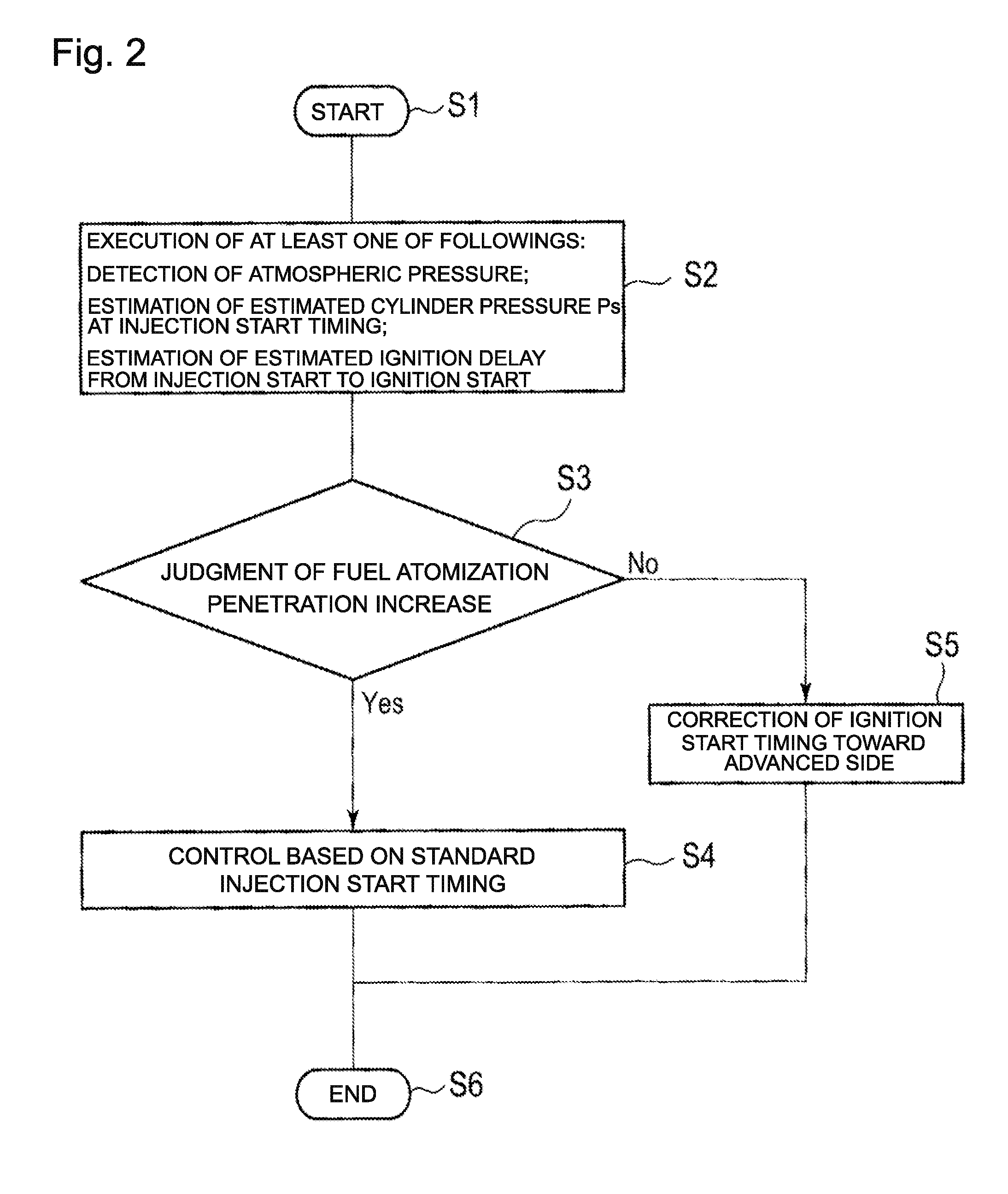
A fuel injection control device provided with: a standard fuel injection timing setting unit 41 which previously sets a standard fuel injection timing with respect to engine speed and fuel injection quantity; an injection penetration judging unit 45 which judges whether or not the penetration of the fuel atomization in a cylinder is in an increasing condition, by use of at least one out of a detected ambient pressure from an ambient pressure sensor, an estimated cylinder pressure at an injection start timing, and an estimated ignition delay from an injection start timing to a combustion start timing; and a fuel injection timing correction unit 43 which corrects the fuel injection timing toward an advanced timing angle and constrains the penetration of the fuel atomization, in a case where the penetration judging unit judges that the penetration of the fuel atomization is in an increasing condition.

Description

BACKGROUND OF THE INVENTION[0001]1. Field of the Invention[0002]The present invention relates to a fuel injection control device as well as a fuel injection control method of a diesel engine.[0003]2. Background of the Invention[0004]As an exhaust gas emission control measure for a diesel engine, NOx reduction is essential. As an approach of NOx reduction, the timing retard of the fuel injection timing is often applied so that the NOx reduction is performed by reducing the combustion temperature in the cylinder. The timing retard is often required especially for an engine in which EGR (Exhaust Gas Recirculation) is not performed.[0005]However, when the injection-timing is excessively retarded, the combustion efficiency is deteriorated and soot is easily generated; further, in response to the increase of fuel atomization penetration or combustion flame penetration, the possibility that the soot comes in contact with a cylinder liner is increased. Hereby, the increase of fuel atomizati...

Claims


Application Information

Patent Timeline
Patent Type & Authority Applications(United States)
IPC IPC(8): F02D41/30
CPCF02D35/024F02D35/028F02D41/401F02D2200/0618Y02T10/44F02D41/30F02D2200/703Y02T10/40F02D41/04F02D41/40F02D45/00
Inventor YAMADA, SATOSHI
Owner MITSUBISHI HEAVY IND ENGINE & TURBOCHARGER LTD
Learn More