
System for Interconnecting Standard Telephony Communications Equipment to Internet

a technology of interconnection and communication equipment, applied in the field of standard telephony communications interconnection system, can solve the problems of reducing and laborious creation and testing of new telephone circuits, so as to maximize the efficiency of communication resources and reduce costs

Inactive Publication Date: 2012-05-24
BEAR CREEK TECH
View PDF0 Cites 2 Cited by
  • Summary
  • Abstract
  • Description
  • Claims
  • Application Information

AI Technical Summary

Benefits of technology

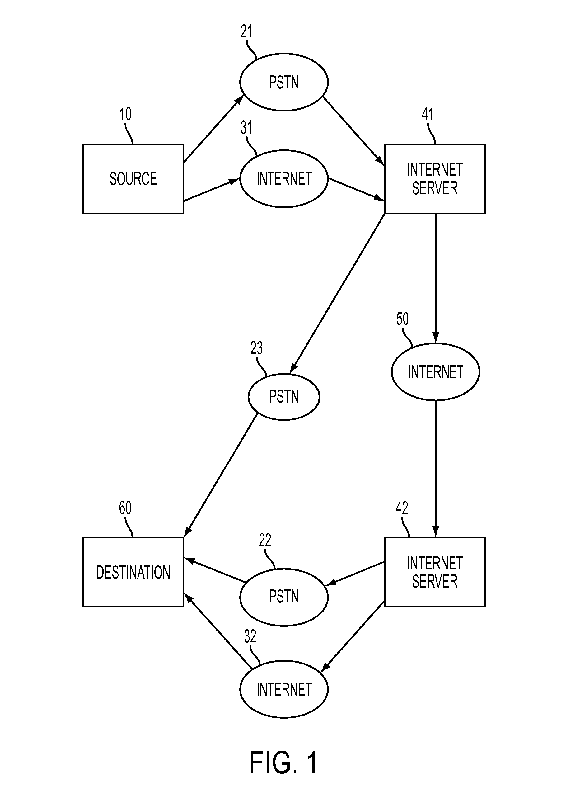
"The present invention aims to improve communication systems by maximizing resource usage, reducing costs, and providing versatility. It allows for better Internet communication using standard telephony equipment and takes advantage of existing infrastructure. The invention also manages communication costs by identifying and utilizing alternative lower cost communication pathways. Overall, the invention provides a system for efficient and cost-effective communication between sources and destinations."

Problems solved by technology

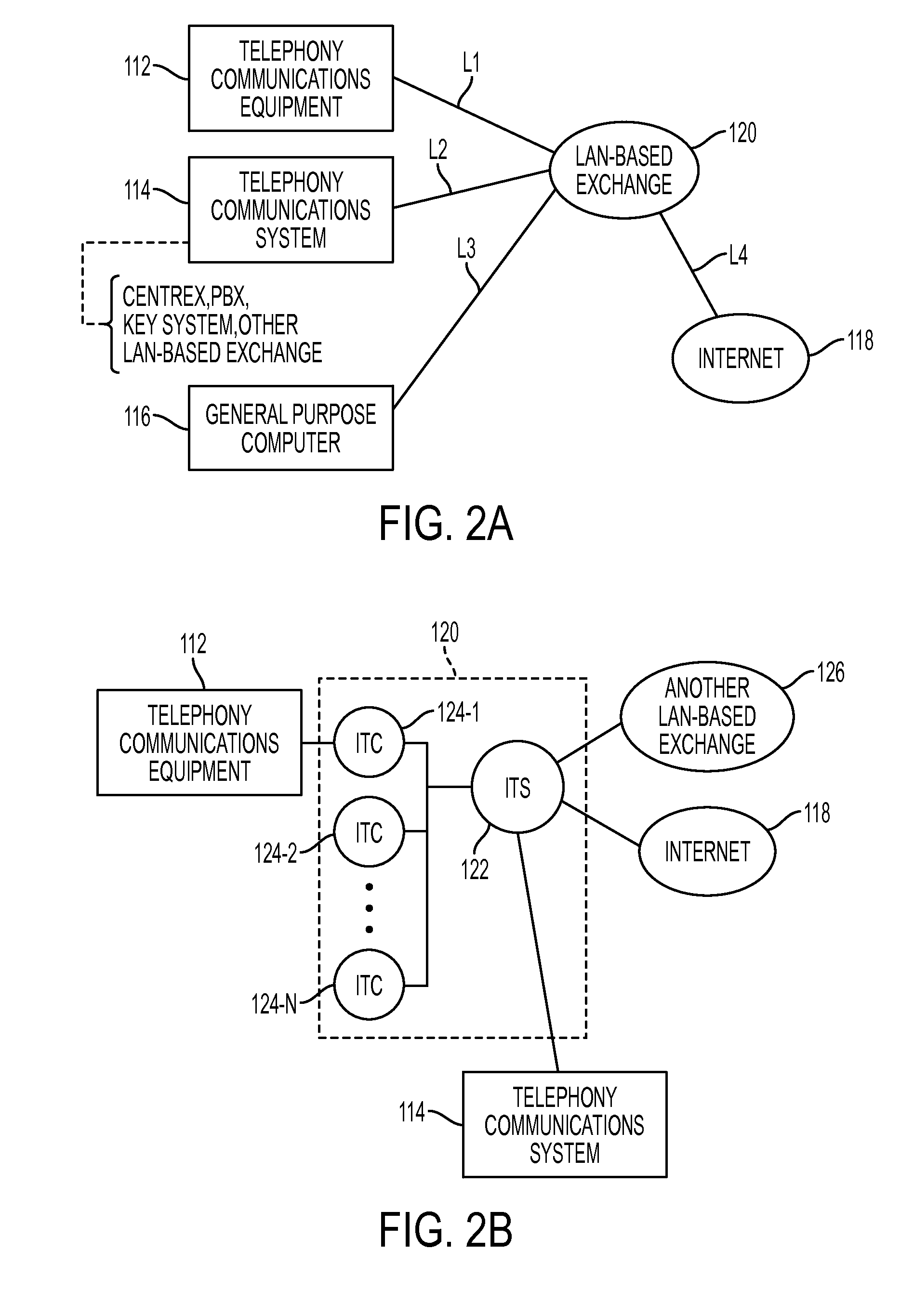
It is costly to reconfigure a given traditional telephony communications system, such as a centrex system, a PBX system, or a key telephone system.
As just one example, the creation and testing of a new telephone circuit will be quite labor-intensive, requiring such actions as locating the switch, finding a suitable and available wiring connection to establish the telephone circuit, making many cross-connections between and / or splicing of cables to route the wiring to the desired end destination, and performing different testing and verification procedures to ensure that a proper connection is made.
If at any critical point in the path of a circuit, the available lines reach their full capacity, new lines will need to be installed to accommodate new telephony circuits, or the circuit must be diverted in a less than optimal manner to utilize existing cable facilities.

Method used


Image

  • System for Interconnecting Standard Telephony Communications Equipment to Internet
  • System for Interconnecting Standard Telephony Communications Equipment to Internet
  • System for Interconnecting Standard Telephony Communications Equipment to Internet

Examples


Embodiment Construction

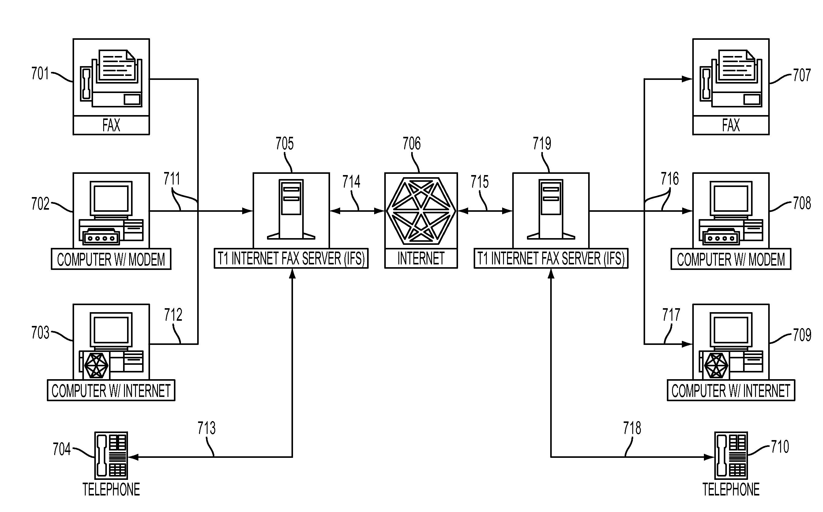
[0047]This disclosure allows individuals, with unmodified, standard fax equipment to fax to anyone else with unmodified, standard fax equipment regardless of distance. The fax is sent without the aid of a long distance telephone communication connection by creating a temporary, individualized network connection where “network” is taken broadly to mean the entire system required to complete a communication from an originator to a target. This network will use the Internet via two dependent Internet Fax Servers (IFS) local to both the originator and target.

[0048]The system contains several components which actually transmit the fax message and related information, provide eMail notification reports of the status for faxes within the system, provide an accounting of services rendered for both the customer and the telephone company, allow individuals with internet access to “prefer” to receive faxes via eMail from originators using the invention, and control and supervise all of these a...


PUM


Abstract

Apparatus includes a communication predelivery receiver, configured to communicate with and relay both IP addressed overhead and IP addressed payload data from an originating communication device. The communication predelivery receiver includes a screener configured to, when the communication predelivery receiver is in communication with the originating communication device, receive certain data including first IP addressed data and second IP addressed data of corresponding first and second initiated communications. The communication predelivery receiver is configured and connected within a network so the first IP addressed data and the second IP addressed data are processed differently. For the first initiated communication, the first payload data is converted, after the point in time at which the screener received the first IP addressed data, from IP addressed first payload data to another network signal. For the second initiated communication, the second payload data is delivered without so converting the second payload data.

Description

RELATED APPLICATION DATA[0001]This Application is related to, and claims priority under 35 U.S.C. §119 with respect to, Provisional Application No. 60 / 012,896 filed Mar. 6, 1996 and Provisional Application No. 60 / 013,240 filed Mar. 11, 1996, the contents of each of these provisional applications being hereby expressly incorporated herein by reference in their entirety.[0002]This application is a continuation of, and claims priority to U.S. application Ser. No. 13 / 027,232 filed Feb. 14, 2011, which is a continuation of, and claims priority to U.S. application Ser. Nos. 11 / 253,129 filed Oct. 18, 2005 (issued as U.S. Pat. No. 7,889,722), 10 / 770,808 filed Feb. 3, 2004 (issued as U.S. Pat. No. 6,985,494), 10 / 279,645 filed Oct. 24, 2002 (now abandoned), and 08 / 812,745 filed Mar. 6, 1997 (now abandoned), the contents of which are being hereby expressly incorporated by reference herein in their entireties.RESERVATION OF COPYRIGHT[0003]The disclosure of this patent document contains material...

Claims


Application Information

Patent Timeline
Patent Type & Authority Applications(United States)
IPC IPC(8): H04M11/00G06F3/12
CPCH04L29/06027H04M7/1205H04L65/605H04L65/1063H04L65/1053H04L65/1073H04N1/32427H04N1/32406H04N1/0022H04M3/533H04L51/066H04L12/5835H04N2201/0093H04N2201/0067H04N1/001H04N1/00228H04N1/00302H04L65/765H04L65/1101
Inventor THOMPSON, JOSEPH B.
Owner BEAR CREEK TECH
Learn More