Radar apparatus and method of detecting target object
- Summary
- Abstract
- Description
- Claims
- Application Information
AI Technical Summary
Benefits of technology
Problems solved by technology
Method used
Image
Examples
first embodiment
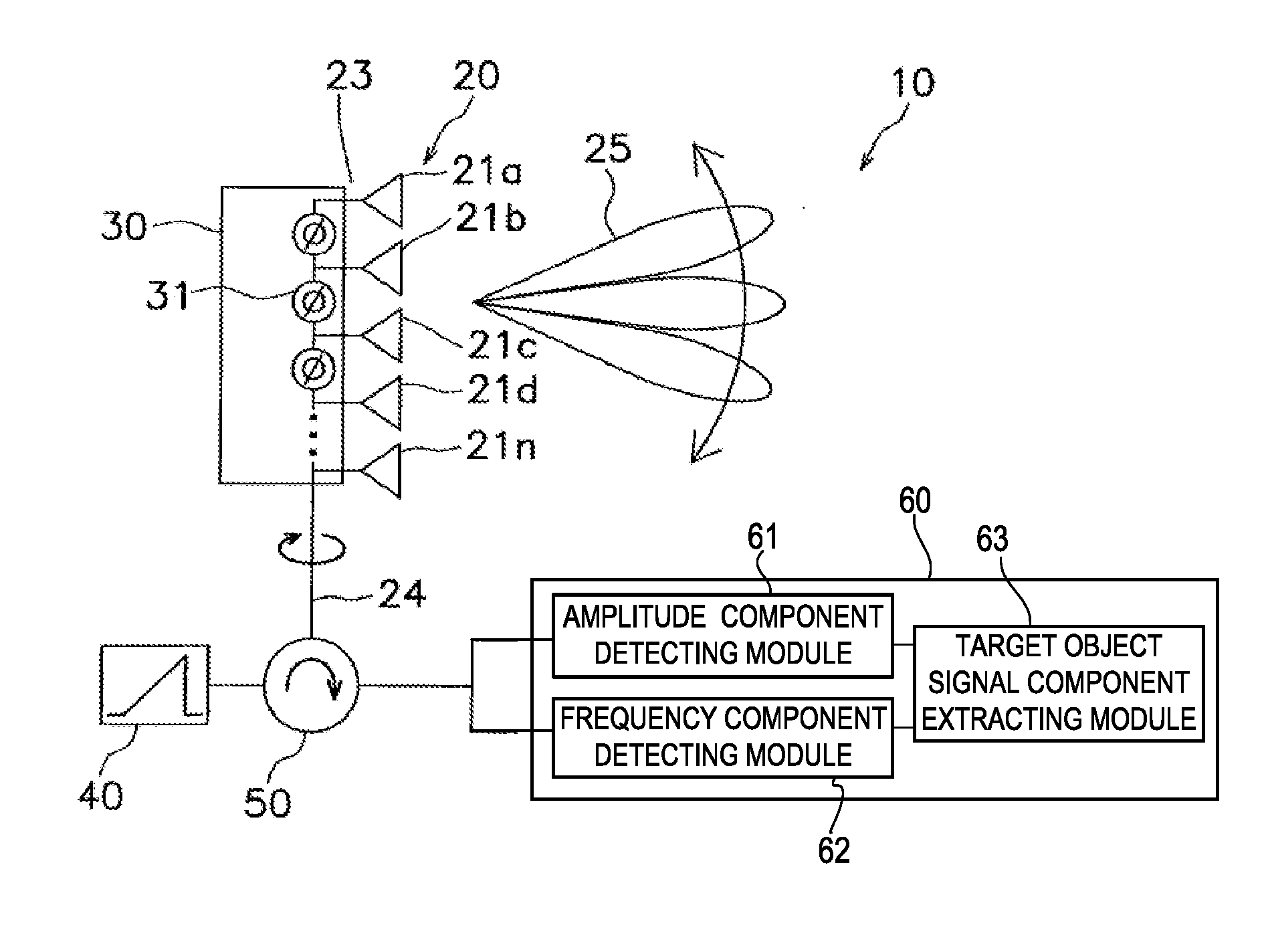
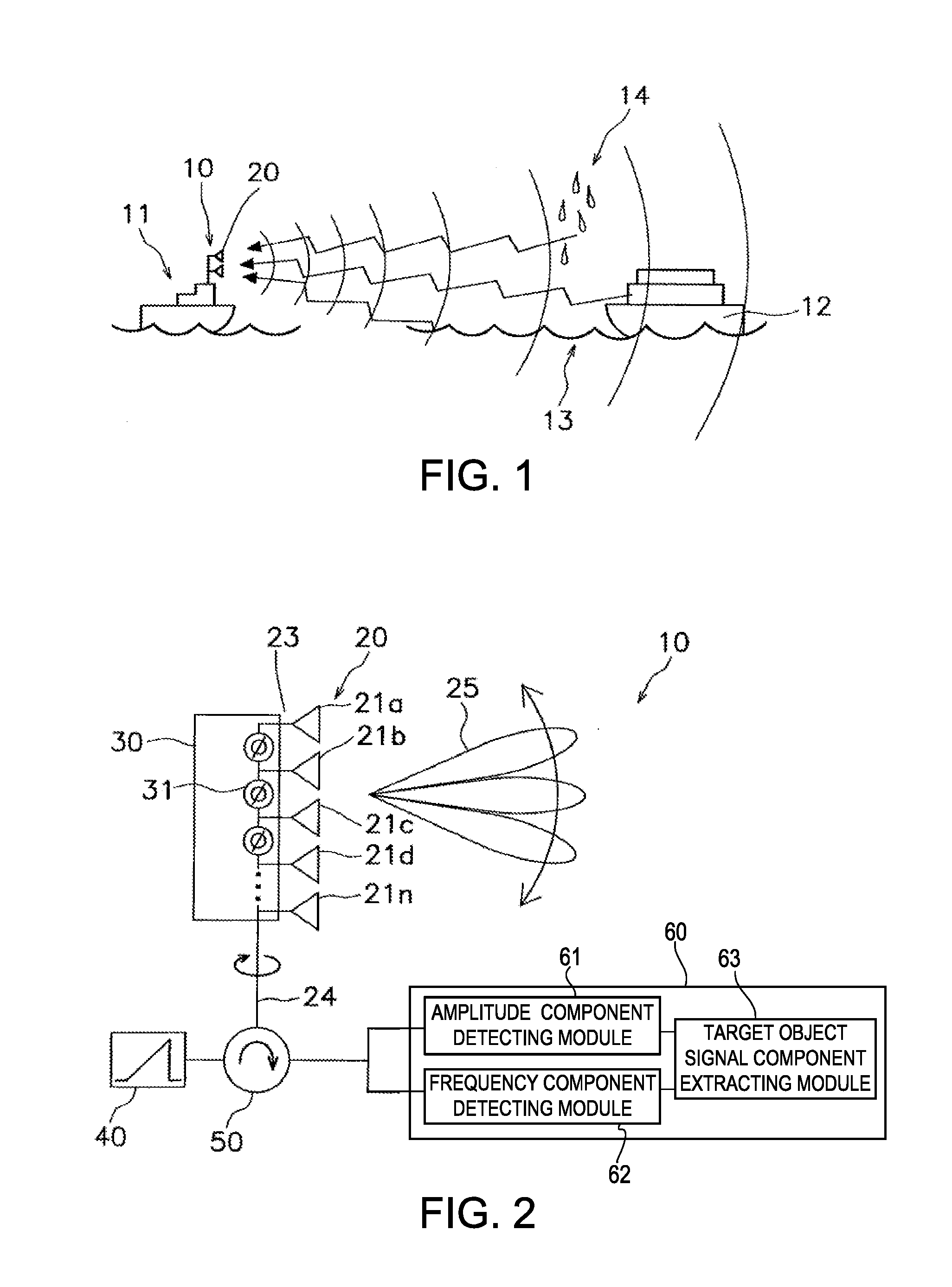
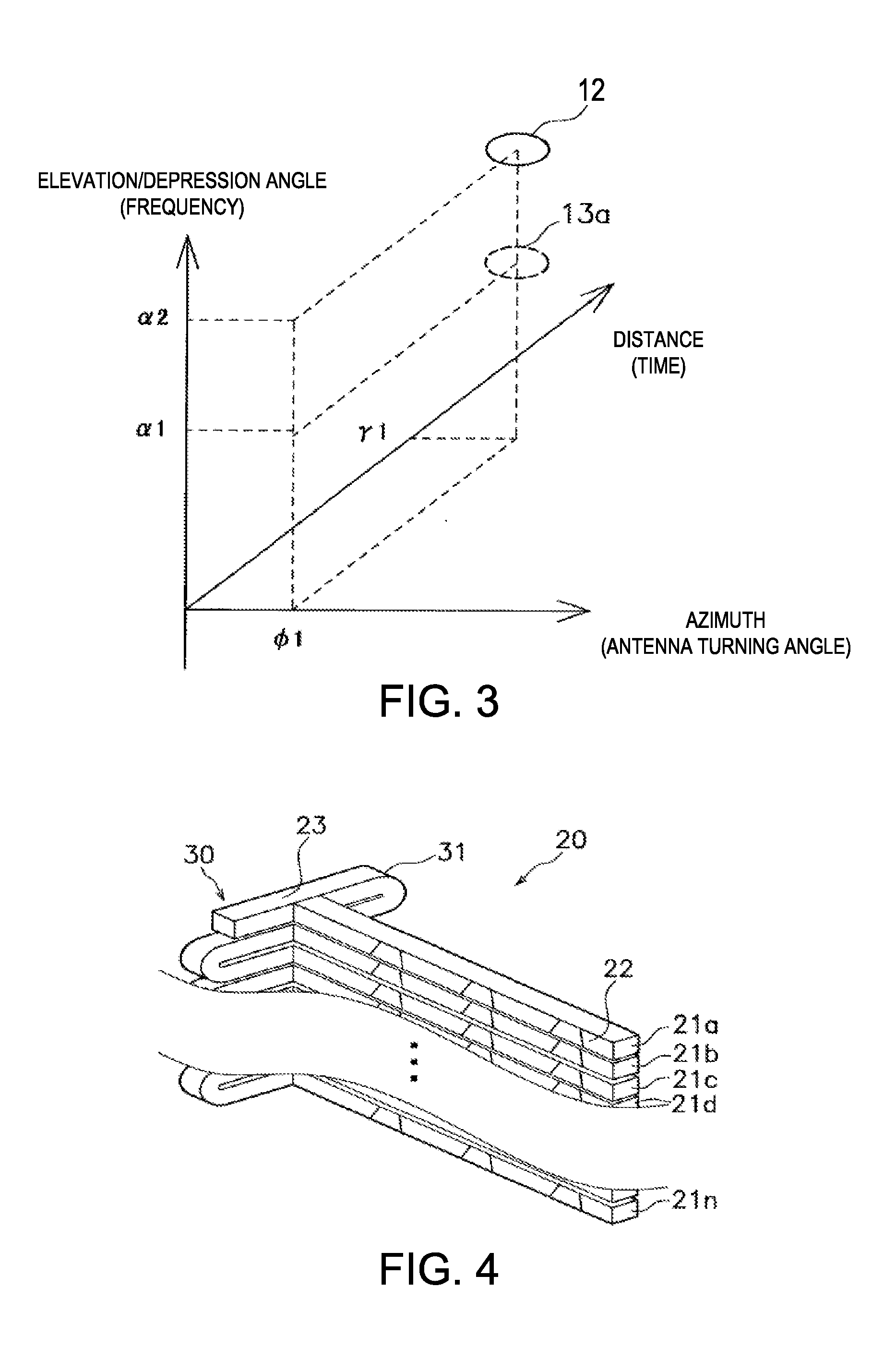
[0043]Hereinafter, a radar apparatus according to a first embodiment of the present invention is described with reference to FIGS. 1 to 17. A ship radar apparatus 10 is provided as an example of using the radar apparatus of the first embodiment. FIG. 1 is a conceptual view explaining a usage example of the ship radar apparatus 10. A ship 11 (hereinafter, referred to as “the ship 11”) in FIG. 1 is mounted with the ship radar apparatus 10. In the ship 11, the ship radar apparatus 10 distinguishes a reflection echo of other ships 12 (target object) among reflection echoes of a sea surface 13, rain 14 and / or fog, for example, to detect the other ships 12.
[0044]Then the detected ship 12 is normally displayed on a display device (not illustrated) including a liquid crystal display. In a radar image to be displayed, a surrounding range of, for example, 360° centered on a position of the radar apparatus (antenna) is displayed, and the origin of the displayed image corresponds to the positio...
modified example 1-1
[0072]The radar apparatus 10 of the above embodiment is configured to detect the target object signal component 71 without considering movement (rolling, pitching) of the ship 11 mounted with the radar apparatus 10. However, when the detection performed for the signal component which is transmitted and received in a state where the ship 11 inclines, the antenna 20 is also inclined and the target object signal component may not be correctly detected from the reception signal. Therefore, a correction of inclination of the ship 11 is preferred to be performed by using, for example, an inclination detecting sensor for detecting an inclined angle of the ship 11. In a modified example described below, a reception module 60A is provided so that the inclined angle of the ship 11 is obtained from the data provided to the target object signal component extracting module 63.
[0073]FIG. 12A shows an area Ar1 of the reception signal when scanning a range of ±10° in the elevation / depression angle ...
modified example 1-2
[0078]As shown in FIG. 13, a radar apparatus 10B according to another modified example of the first embodiment is provided with a reception module 60B having a target object estimating module 65, in addition to the configuration of the radar apparatus 10. The target object estimating module 65 acquires the data from the target object signal component extracting module 63 and estimates whether the acquired data is from a target object. The estimation by the target object estimating module 65 is for estimating the two-dotted chain line DL1 shown in FIG. 12A, that is an envelope curve indicating the sea surface, and estimating whether the data is from the target object based on the envelope curve. The envelope curve can be obtained by, for example, similar to the method in the modified example 1-1, obtaining a difference between the theoretical value and the actual measurement value. The radar apparatus 10B is mounted on the ship 11 shown in FIG. 1 same as the radar apparatuses 10 and ...
PUM
 Abstract
Description
Claims
Application Information
 - R&D
- Intellectual Property
- Life Sciences
- Materials
- Tech Scout
- Unparalleled Data Quality
- Higher Quality Content
- 60% Fewer Hallucinations
Browse by: Latest US Patents, China's latest patents, Technical Efficacy Thesaurus, Application Domain, Technology Topic, Popular Technical Reports.
© 2025 PatSnap. All rights reserved.Legal|Privacy policy|Modern Slavery Act Transparency Statement|Sitemap|About US| Contact US: help@patsnap.com


