
Memory mirroring with memory compression

a memory mirroring and memory compression technology, applied in error detection/correction, redundancy hardware error correction, instruments, etc., can solve the problems of limiting the overall memory storage, reducing system performance, and significant manufacturing costs, so as to reduce the cost overhead of memory mirroring, increase the amount of mirrored and primary memory available, and avoid memory access latency penalties

Active Publication Date: 2012-05-17
LENOVO GLOBAL TECH INT LTD
View PDF14 Cites 21 Cited by
  • Summary
  • Abstract
  • Description
  • Claims
  • Application Information

AI Technical Summary

Benefits of technology

This patent describes how to make computer systems faster and more efficient by compressing memory to create more storage space without adding any extra hardware or increasing latency. By doing this, we can provide larger amounts of main memory while reducing the cost of memory mirroring which means that multiple copies of data are stored across different parts of the system. This technique allows us to have better performance and lower costs when dealing with large amounts of data.

Problems solved by technology

This patent discusses a technique called memory mirroring which involves keeping an extra copy of data in computer memory. However, this can use up a lot of expensive hardware and reduce the amount of actual memory available for other uses. Additionally, it can make things slower because there's less space left for everything else.

Method used


Image

  • Memory mirroring with memory compression
  • Memory mirroring with memory compression
  • Memory mirroring with memory compression

Examples


Embodiment Construction

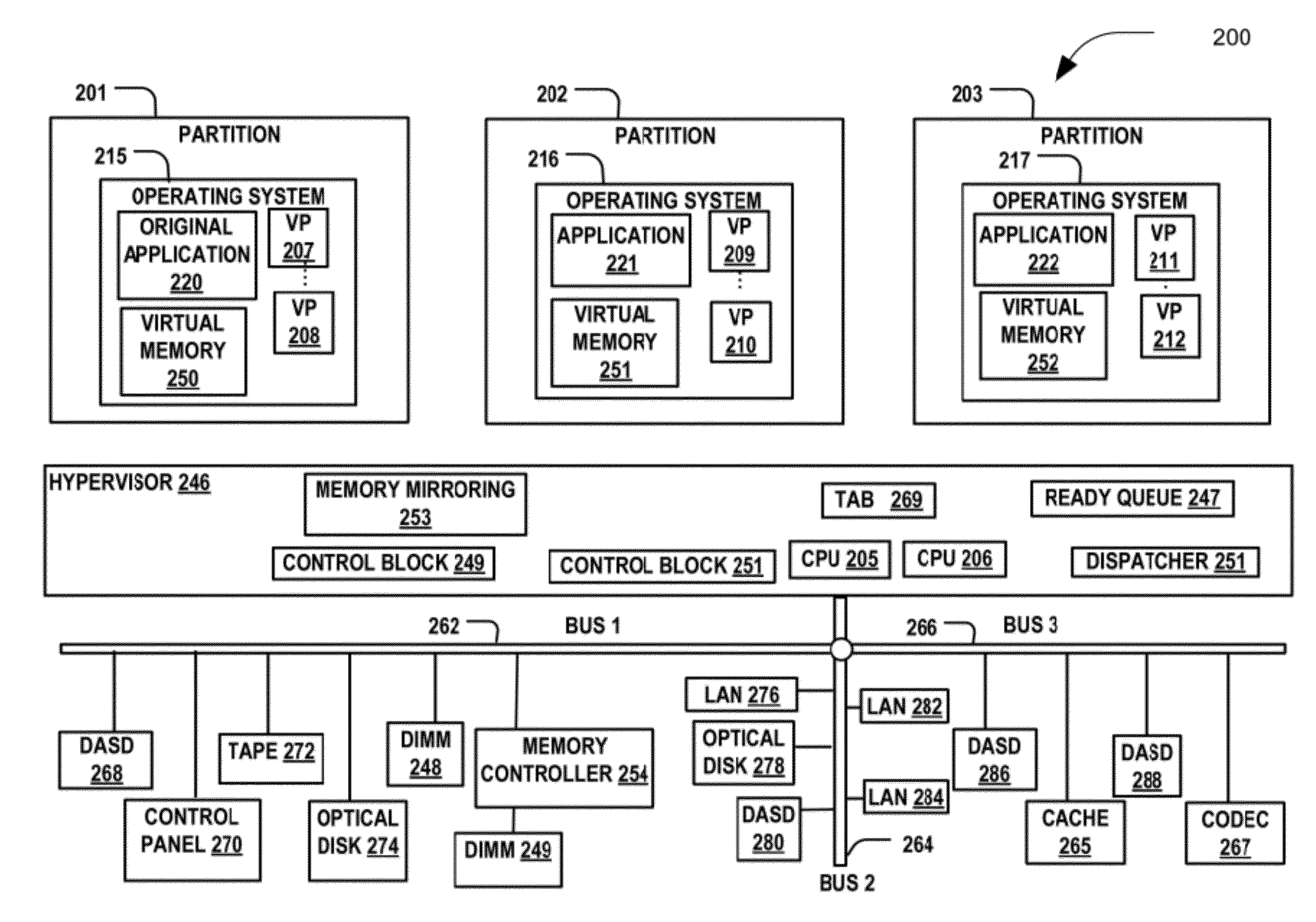
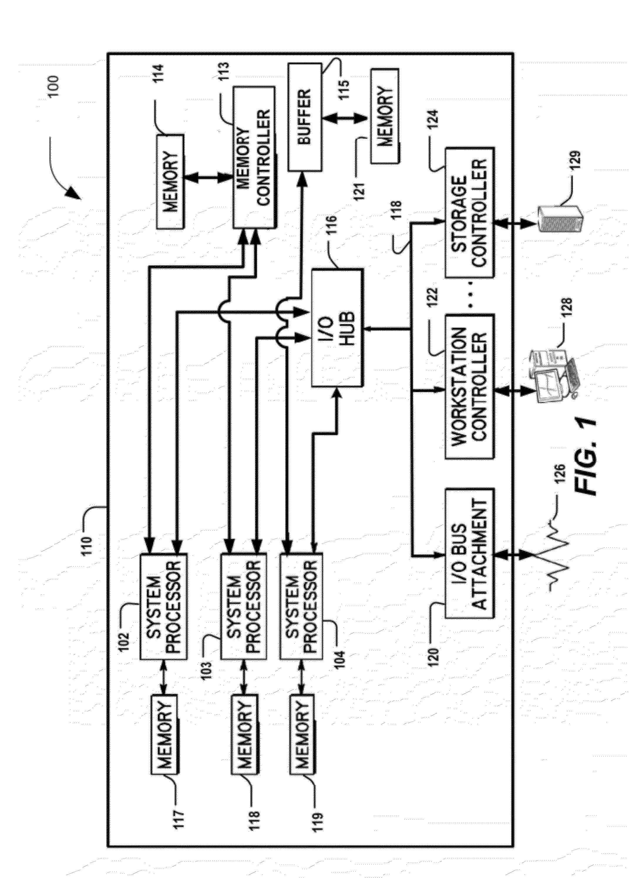
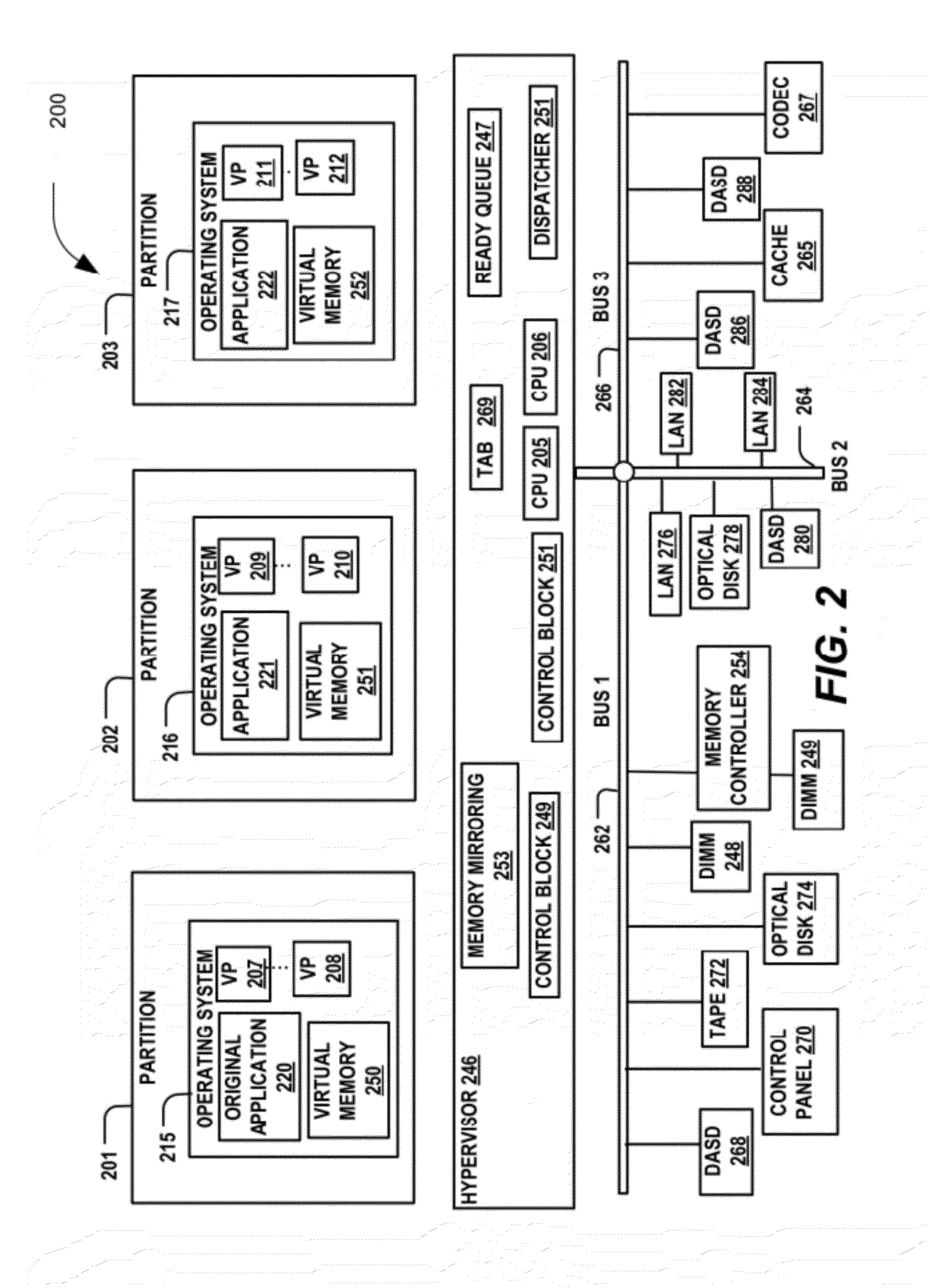
[0013]A particular embodiment uses memory compression to lower the size and cost associated with memory mirroring by compressing mirrored memory and not primary memory. The mirrored data may only be accessed when the primary memory fails. For normal operations (e.g., operations having no or an acceptable number of errors), there may be no decompression latency or performance overhead when uncompressed primary data is accessed.

[0014]Errors may be detected in the primary memory. In response to the detected failure, a processor may seamlessly transition from executing out of the uncompressed primary memory to the compressed mirrored memory. The processor may continue to operate without crashing when the primary memory fails, though at a degraded level of performance due to the decompression latency overhead. The defective primary memory may be repaired or replaced at a convenient time to return the computer back to full performance.

[0015]Switching from the primary memory to the mirrore...


PUM


Abstract

Systems and methods to manage memory are provided. A particular method may include storing data in a primary memory that is in communication with a processor and storing in a mirrored data in a mirrored memory. The mirrored data may be compressed, and the mirrored memory may be in communication with the processor. A failure condition associated with the data of the primary memory may be detected. In response to the detected failure condition, the mirrored data in the mirrored memory may be accessed.

Description


Claims


Application Information

Patent Timeline
Owner LENOVO GLOBAL TECH INT LTD
Learn More