
Induction heating device for fuel cell system

a fuel cell and heating device technology, applied in the field of induction heating devices for fuel cell systems, can solve the problems of increasing manufacturing costs, difficult to ensure a space for mounting heating devices, and reducing the assemblability and maintainability of this system, so as to achieve rapid heating and improve insulation performan

Active Publication Date: 2012-05-17
HYUNDAI MOTOR CO LTD
View PDF6 Cites 41 Cited by
  • Summary
  • Abstract
  • Description
  • Claims
  • Application Information

AI Technical Summary

Benefits of technology

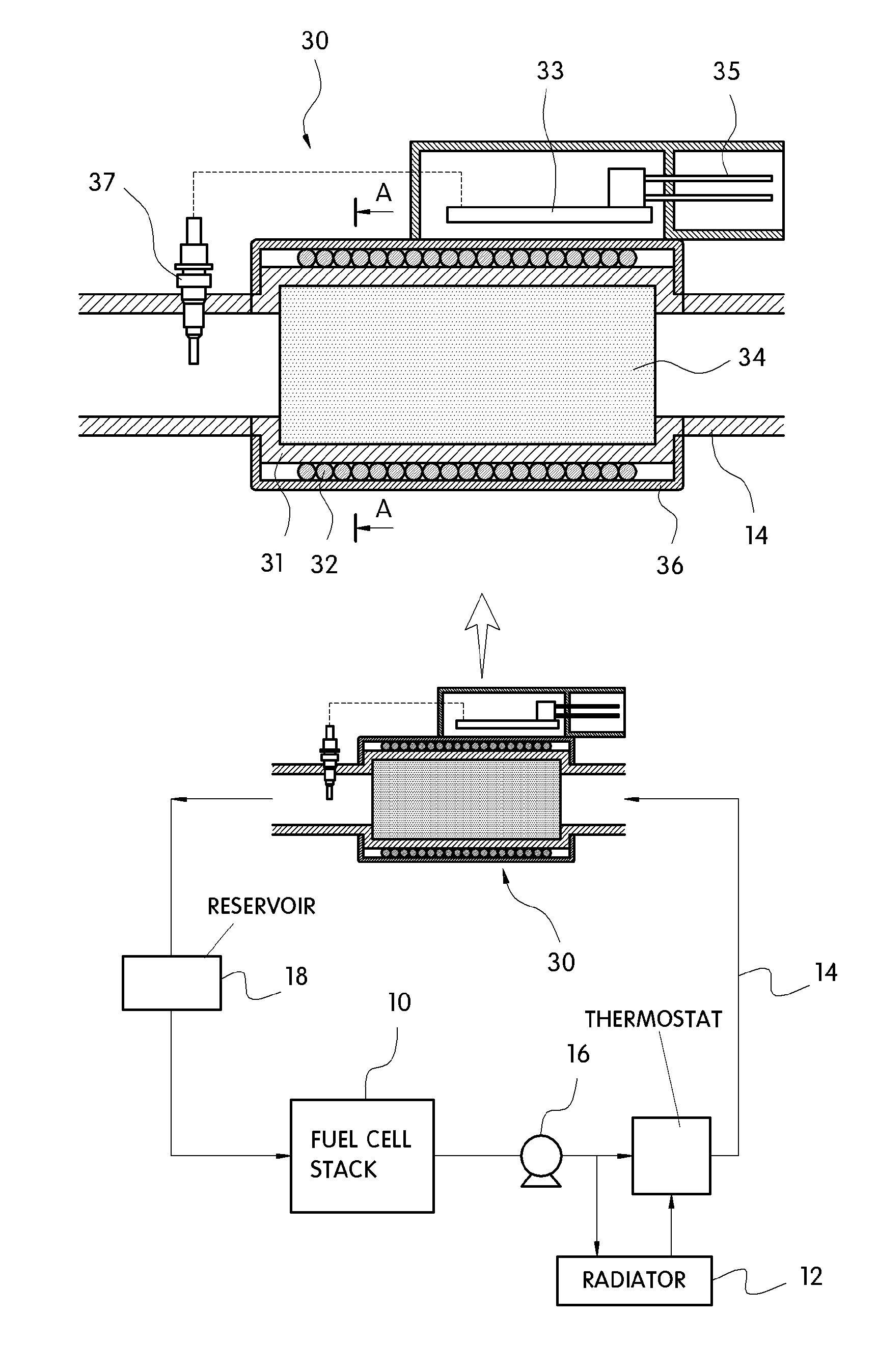
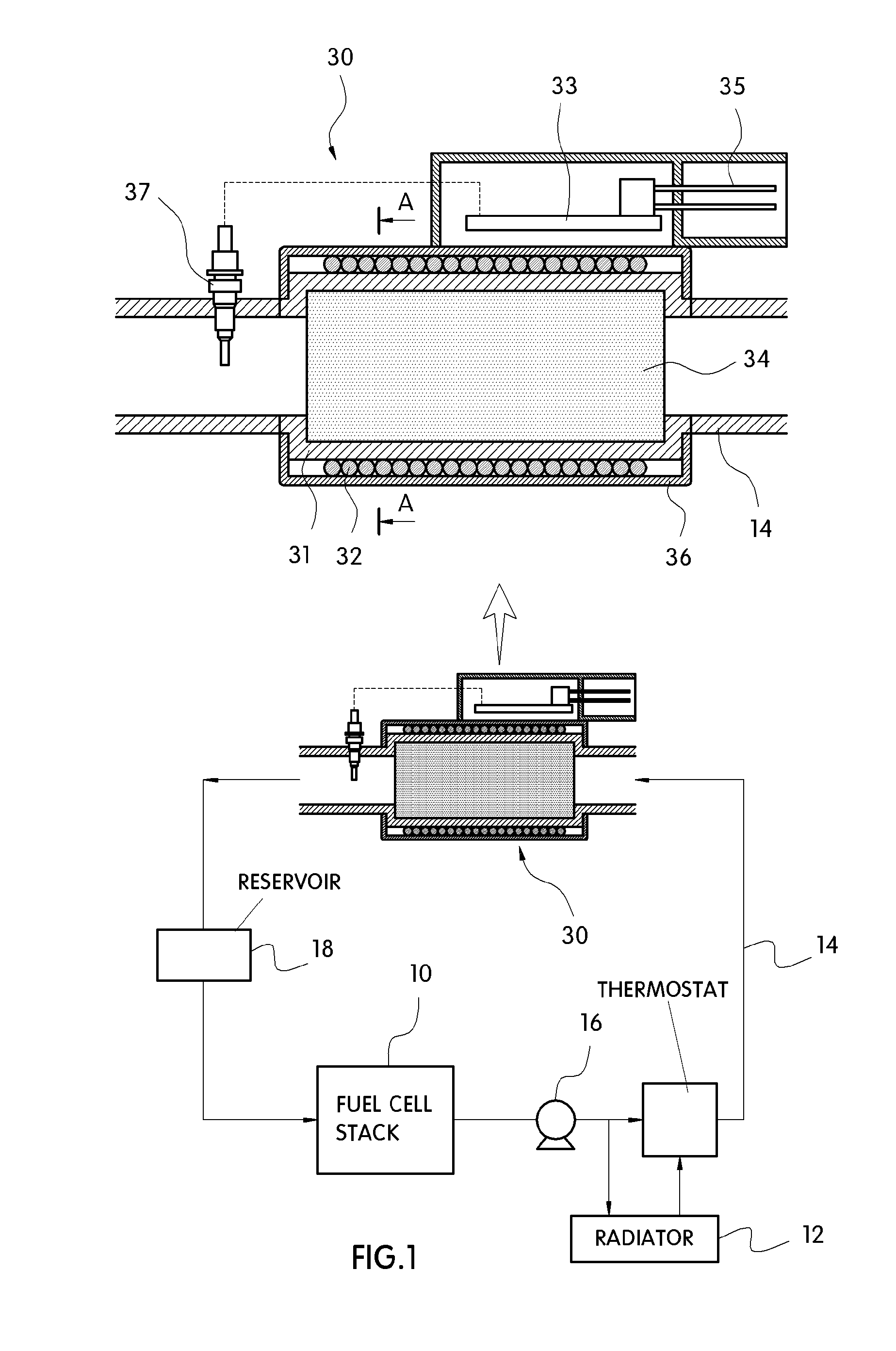
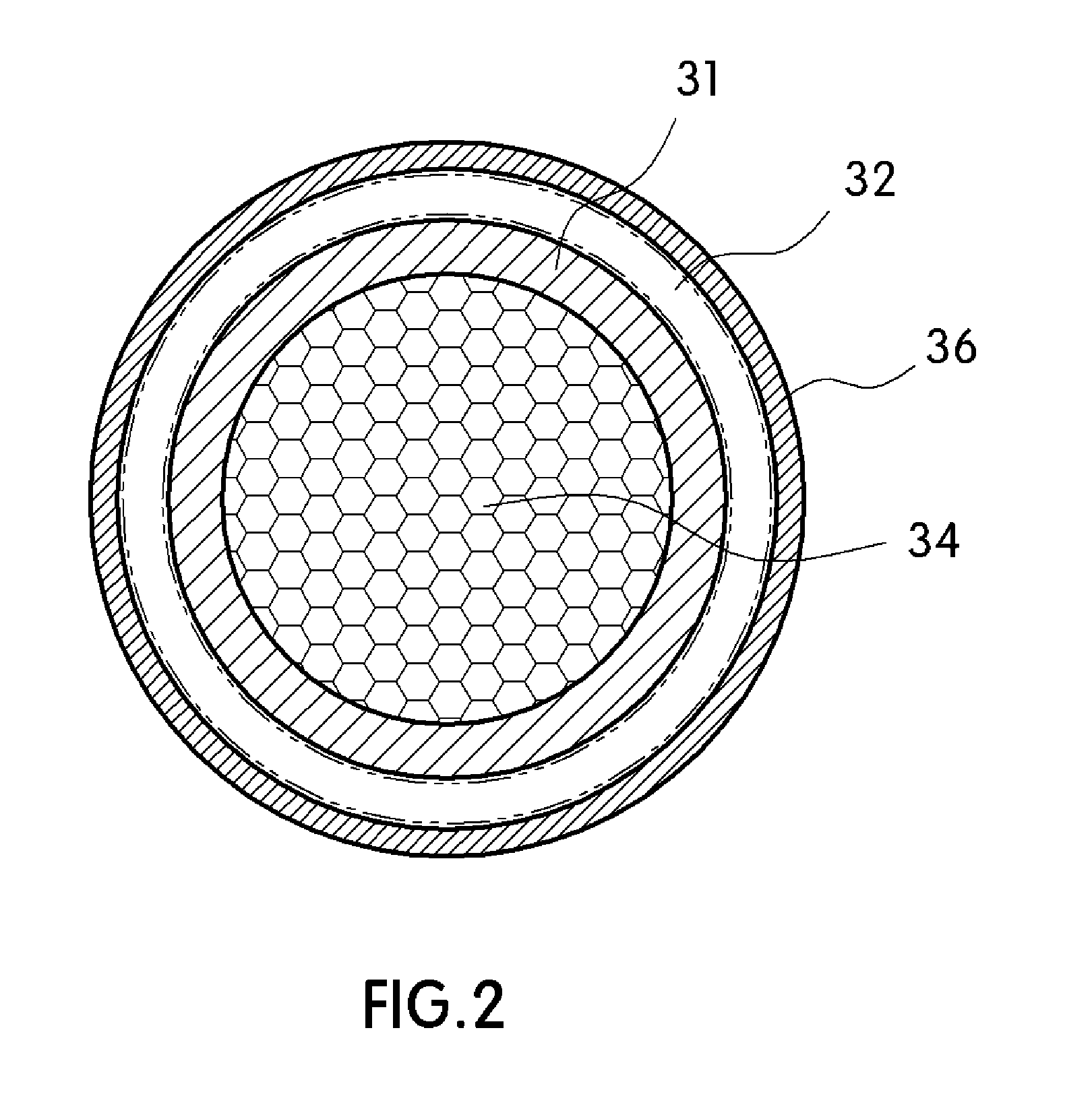
[0018]The present invention provides an induction heating device for a fuel cell system, in which an insulating housing is provided in a coolant circulation line, a heater for heating coolant is provided in the housing, and a high frequency controller for controlling the power consumption of the heater is provided at the outside of the housing such that the coolant can be rapidly heated during cold start-up, allow for precise control the power consumption to depending of the voltage of a fuel cell stack, and improve the insulation performance by separating the heater as a heating unit, which is in contact with the coolant. More specifically, the high frequency controller and a coil are configured as a power unit with respect to the insulating housing.

Problems solved by technology

Therefore, it is difficult to ensure a space for mounting the heating device which has such a large volume in a compact vehicle such as a fuel cell vehicle.
Moreover, the complicated structure increases the manufacturing cost and reduces the assemblability and maintainability of this system.
In addition, the cartridge resistance heaters penetrating the housing are typically sealed with O-rings, and thus when the temperature of the heaters is increased, the coolant may leak due to deformation of the O-rings, thus destroying the insulation.
However, to control the power of the fuel cell stack during cold start-up, this system requires a heater at each resistor and a relay for controlling the heater, which imposes various limitations to the overall system.

Method used


Image

  • Induction heating device for fuel cell system
  • Induction heating device for fuel cell system
  • Induction heating device for fuel cell system

Examples


Embodiment Construction

[0050]Hereinafter reference will now be made in detail to various embodiments of the present invention, examples of which are illustrated in the accompanying drawings and described below. While the invention will be described in conjunction with exemplary embodiments, it will be understood that present description is not intended to limit the invention to those exemplary embodiments. On the contrary, the invention is intended to cover not only the exemplary embodiments, but also various alternatives, modifications, equivalents and other embodiments, which may be included within the spirit and scope of the invention as defined by the appended claims.

[0051]It is understood that the term “vehicle” or “vehicular” or other similar term as used herein is inclusive of motor vehicles in general such as passenger automobiles including sports utility vehicles (SUV), buses, trucks, various commercial vehicles, watercraft including a variety of boats and ships, aircraft, and the like, and inclu...


PUM


Abstract

The present invention provides an induction heating device for a fuel cell system, which can rapidly heat coolant during cold start-up, control the power consumption depending on the voltage of a fuel cell stack, and ensure the insulation resistance by separating a heating unit, which is in contact with the coolant, from the outside. That is, the present invention provides an induction heating device for a fuel cell system, in which an insulating housing is provided in a coolant circulation line, a heater for heating coolant is provided in the housing, and a high frequency controller for controlling the power consumption of the heater is provided at the outside of the housing such that the coolant can be rapidly heated during cold start-up, precisely control the power consumption depending of the voltage of a fuel cell stack, and improve the insulation performance by separating the heater as a heating unit, which is in contact with the coolant, and the high frequency controller and a coil as a power unit with respect to the insulating housing.

Description

CROSS-REFERENCE TO RELATED APPLICATION[0001]This application claims under 35 U.S.C. §119(a) the benefit of Korean Patent Application No. 10-2010-0112577 filed Nov. 12, 2010, the entire contents of which are incorporated herein by reference.BACKGROUND[0002](a) Technical Field[0003]The present invention relates to an induction heating device for a fuel cell system. More particularly, it relates to an induction heating device for a fuel cell system, which can to rapidly heat coolant during cold start-up, control the power consumption depending on the voltage of a fuel cell stack, and ensure the insulation resistance by separating a heating unit, which is in contact with the coolant, from the outside.[0004](b) Background Art[0005]A conventional fuel cell system comprises a fuel cell stack for generating electricity and heat in the form of reaction products via an electrochemical reaction. In a fuel cell system, the chemical energy of a fuel is converted into electrically energy. Typical...

Claims


Application Information

Patent Timeline
IPC IPC(8): H05B6/04
CPCH01M8/04029H01M8/04037H01M8/04559H01M8/04611H01M8/04723Y02T90/32H01M8/04985H01M2250/20H05B6/108Y02E60/50H01M8/04738H01M8/04953Y02T90/40
Inventor KIM, SEONG KYUNKO, HAENG JINHAN, SU DONGNAM, GI YOUNGKIM, YUN SEOK
Owner HYUNDAI MOTOR CO LTD
Learn More