
Input device and method for detecting switch of input device

a technology of input device and input device, which is applied in the direction of relays, transportation and packaging, and static coding, etc., can solve the problems of difficult to obtain an input device provided with a large number of switches, unable to detect operated switches, and incapable of carrying out a variety of operations accurately

Active Publication Date: 2012-05-10
PANASONIC INTELLECTUAL PROPERTY MANAGEMENT CO LTD
View PDF5 Cites 12 Cited by
  • Summary
  • Abstract
  • Description
  • Claims
  • Application Information

AI Technical Summary

Benefits of technology

[0027]An input device includes a resistor group, an input terminal, a plurality of switches, and a control unit. The resistor group includes a plurality of resistors connected in series. The input terminal is connected to one end of the resistor group. Each switch of the plurality of switches has one end connected to each resistor of the plurality of resistors at an opposite side viewed from the input terminal an

Problems solved by technology

Therefore, in an input device having a plurality of switches, the operated switch may not be able to be detected.
As a result, it is difficult to obtain an input device provided with a large number of switches and capable of carrying out a variety of operations accurately.

Method used


Image

  • Input device and method for detecting switch of input device
  • Input device and method for detecting switch of input device
  • Input device and method for detecting switch of input device

Examples


Embodiment Construction

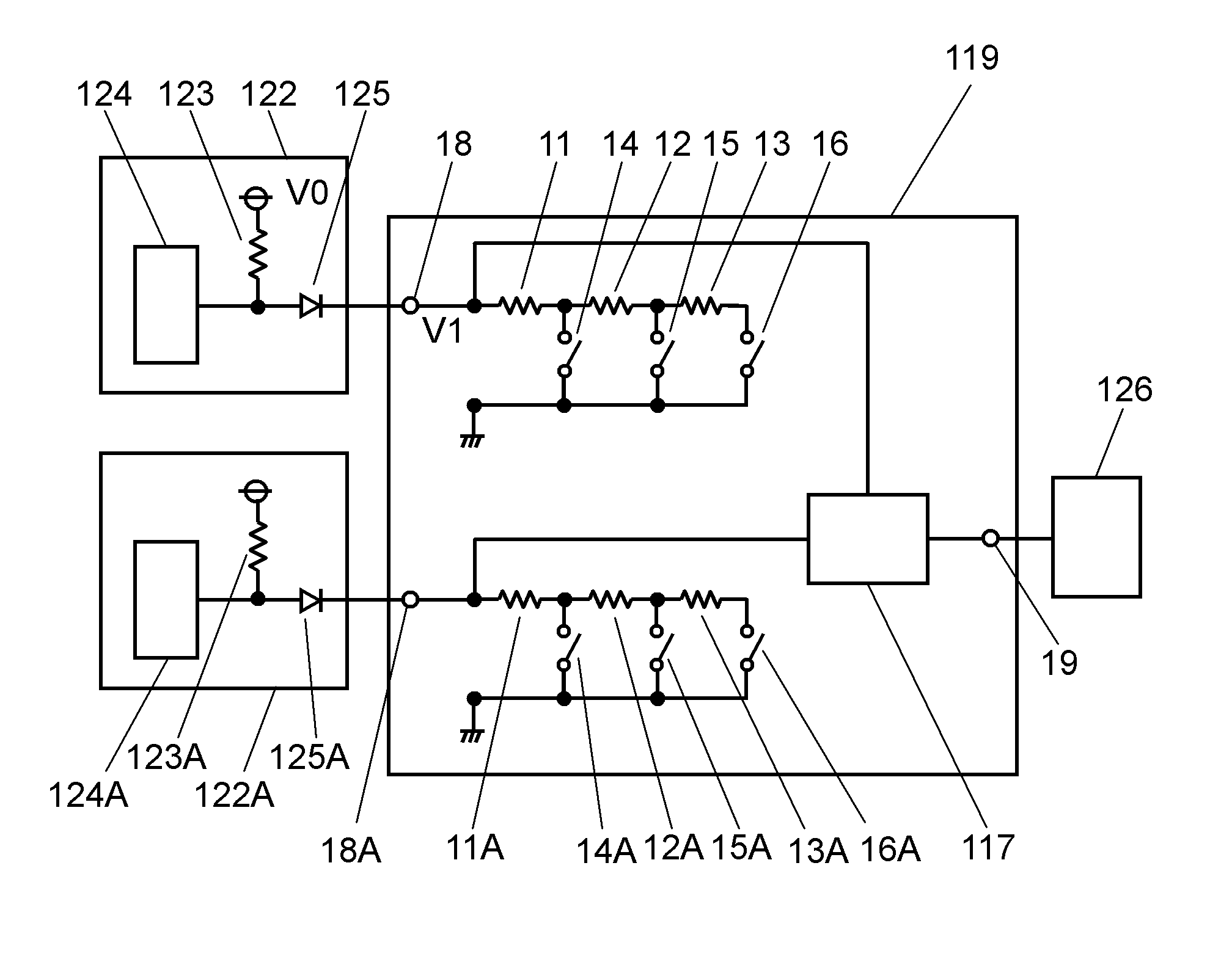
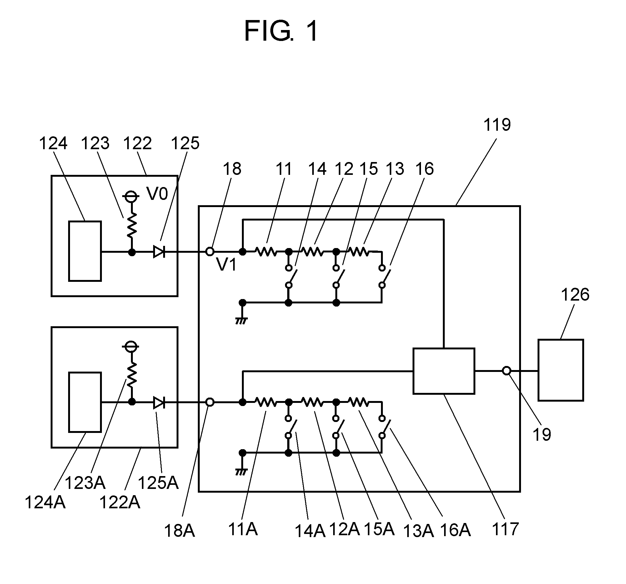
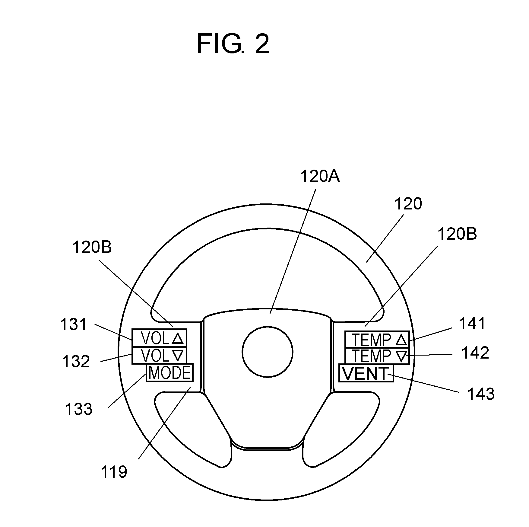
[0032]FIG. 1 is a circuit block diagram of input device 119 in accordance with an embodiment of the present invention. FIG. 2 is a front view of a steering wheel using input device 119 in accordance with the embodiment of the present invention. Input device 119 includes a plurality of resistors 11 to 13 and resistors 11A to 13A, a plurality of switches 14 to 16 and switches 14A to 16A, and control unit 117.

[0033]A plurality of resistors 11, 12, and 13 such as a fixed resistor are connected in series on a wiring board (not shown) to configure a resistor group. A plurality of wiring patterns are formed on the upper and lower surfaces of the wiring board.

[0034]Furthermore, switches 14, 15, and 16 such as a push switch are mounted on the wiring board. One end of switch 14 is connected between resistor 11 and resistor 12, one end of switch 15 is connected between resistor 12 and resistor 13, and one end of switch 16 is connected to resistor 13, respectively, by the wiring pattern. The ot...


PUM


Abstract

An input device includes a resistor group, an input terminal, a plurality of switches, and a control unit. The resistor group includes a plurality of resistors connected in series. The input terminal is connected to one end of the resistor group. Each switch of the plurality of switches has one end connected to each resistor of the plurality of resistors at an opposite side viewed from the input terminal and the other end grounded. The control unit detects an applied voltage to the input terminal when the plurality of switches are all turned off. Furthermore, the control unit detects an output voltage from the input terminal when any of the plurality of switches is turned on, and detects a switch that is turned on among the plurality of switches based on a voltage ratio of the output voltage to the applied voltage.

Description

BACKGROUND OF THE INVENTION[0001]1. Field of the Invention[0002]The present invention relates to an input device for various electronic equipment and a method for detecting a switch of the input device.[0003]2. Background Art[0004]Recently, automobiles equipped with an input device such as a steering switch in the vicinity of a steering wheel have been developed. A user can operate electronic equipment such as an audio system and an air conditioner by operating the input device by the finger in a state in which the user holds the steering wheel. In such automobiles, an input device capable of reliable operation without an operation error has been demanded.[0005]FIG. 3 is a circuit block diagram of a conventional input device. FIG. 4 is a front view of a steering wheel using the conventional input device.[0006]A plurality of resistors 1, 2, and 3 such as a fixed resistor are mounted on a wiring board (not shown), and connected in series. A plurality of wiring patterns are formed on t...

Claims


Application Information

Patent Timeline
IPC IPC(8): H01H47/00
CPCH01H13/70H01H2231/026H03M11/24H01H2239/03H01H2239/012
Inventor IBE, TAKAFUMI
Owner PANASONIC INTELLECTUAL PROPERTY MANAGEMENT CO LTD
Learn More