
Operation control device and operation control method for fuel cell power plant

a fuel cell and power plant technology, applied in the direction of fuel cells, electrochemical generators, electrical devices, etc., can solve the problems of reducing the amount of anode gas that can be used by an anode, and exacerbated adverse effects of pressure pulsation, so as to reduce the amount of anode gas that can be used by an anode, and reducing the generated power

Active Publication Date: 2012-05-03
NISSAN MOTOR CO LTD
View PDF2 Cites 23 Cited by
  • Summary
  • Abstract
  • Description
  • Claims
  • Application Information

AI Technical Summary

Benefits of technology

The invention relates to an operation control device for a fuel cell power plant that controls the generated power of a fuel cell stack. The device includes an anode gas supply mechanism that supplies an anode gas containing hydrogen to the fuel cell stack, a sensor that determines whether or not the amount of hydrogen supplied satisfies the amount required to generate the target generated power, and a programmable controller. The programmable controller controls the anode gas supply mechanism to cause the anode gas pressure in the fuel cell stack to pulsate between an upper limit pressure and a lower limit pressure, and corrects the lower limit pressure in an increasing direction when the hydrogen supply amount does not satisfy the amount required to generate the target generated power. The technical effect of this invention is to quickly recover the generated power of the fuel cell stack even when flooding occurs.

Problems solved by technology

According to research conducted by the inventors, anode gas pressure pulsation may exacerbate an adverse effect that flooding in the fuel cell stack has on a power generation capacity.
As a result, it may be impossible to obtain the amount of anode gas required to generate a target amount of power, leading to a reduction in generated power.

Method used


Image

  • Operation control device and operation control method for fuel cell power plant
  • Operation control device and operation control method for fuel cell power plant
  • Operation control device and operation control method for fuel cell power plant

Examples


second embodiment

[0102]Referring to FIGS. 9-11, this invention, relating to the recovery mode sub-routine and the recovery mode upper limit anode gas pressure setting sub-routine executed by the controller 51, will be described.

first embodiment

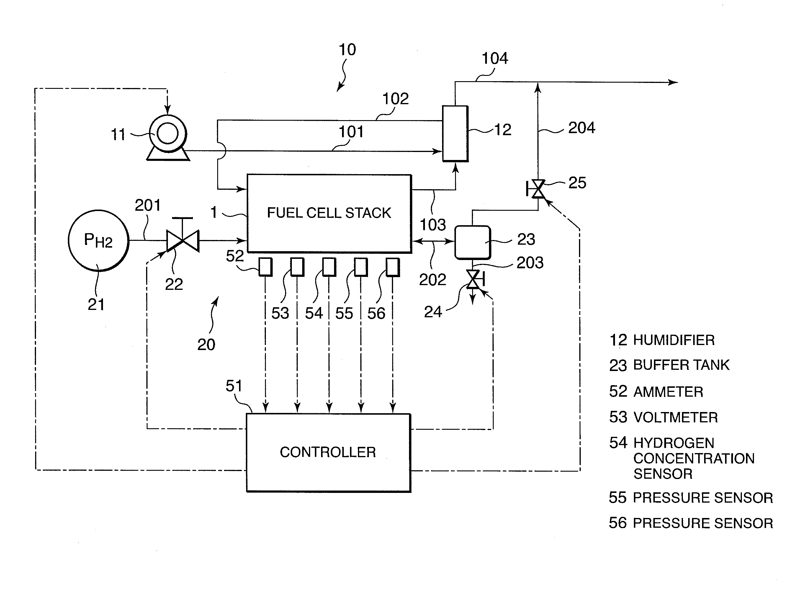
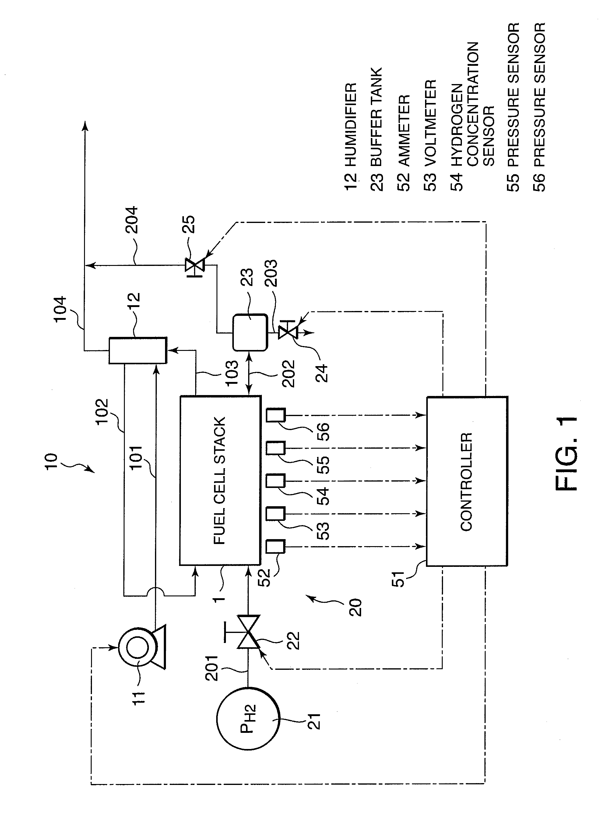
[0103]This embodiment differs from the first embodiment in that a limitation is added to the recovery mode upper limit anode gas pressure Pamax during the recovery mode pressure pulsation operation to ensure that the anode gas pressure does not become excessive relative to the cathode gas pressure. For this purpose, the operation control device according to this embodiment further includes a pressure sensor 56 that detects a cathode gas pressure Pc, as shown in FIG. 1.

[0104]The recovery mode sub-routine according to this embodiment, shown in FIG. 9, corresponds to the recovery mode sub-routine of the first embodiment, shown in FIG. 4, and is executed in the step S4 of the reactant gas pressure control routine of FIG. 3.

[0105]The recovery mode upper limit anode gas pressure setting sub-routine according to this embodiment, shown in FIG. 10, corresponds to the recovery mode upper limit anode gas pressure setting sub-routine of the first embodiment, shown in FIG. 6, and is executed in ...

third embodiment

[0121]Referring to FIGS. 12-14, this invention will be described.

[0122]In the first and second embodiments, the controller 51 controls the anode gas pressure alone, but in this embodiment, the controller 51 controls the cathode gas pressure as well as the anode gas pressure.

[0123]A recovery mode sub-routine according to this embodiment, shown in FIG. 12, corresponds to the recovery mode sub-routine of the first embodiment, shown in FIG. 4, and is executed in the step S4 of the reactant gas pressure control routine of FIG. 3. A step S431 that does not exist in the other embodiments is provided in the recovery mode sub-routine according to this embodiment.

[0124]Referring to FIG. 12, the processing of the steps S401-S411 is identical to that of the first embodiment. Following the processing of one of the steps S405, S406, S410, and S411, the controller 51 executes a cathode gas pressure control sub-routine shown in FIG. 13 in the step S431.

[0125]Referring to FIG. 13, in a step S4311, t...


PUM

PropertyMeasurementUnit
timeaaaaaaaaaa
differential pressure ΔP0aaaaaaaaaa

Abstract

A fuel cell power plant stops anode gas supply to a fuel cell stack 1 by an anode gas supply mechanism 20 when an anode gas pressure in the fuel cell stack 1 reaches an upper limit pressure, and resumes supplying the anode gas by the anode gas supply mechanism 20 when the anode gas pressure in the fuel cell stack 1 lowers to a lower limit pressure. A sensor 52-54 detects if a hydrogen supply amount supplied to the fuel cell stack 1 satisfies a required amount to generate a target generated power, and a controller 51 corrects the lower limit pressure in an increasing direction when the hydrogen supply amount does not satisfy the required amount, thereby suppressing a generated power of the fuel cell stack 1 from reducing even when a flooding takes place in the fuel cell stack 1.

Description

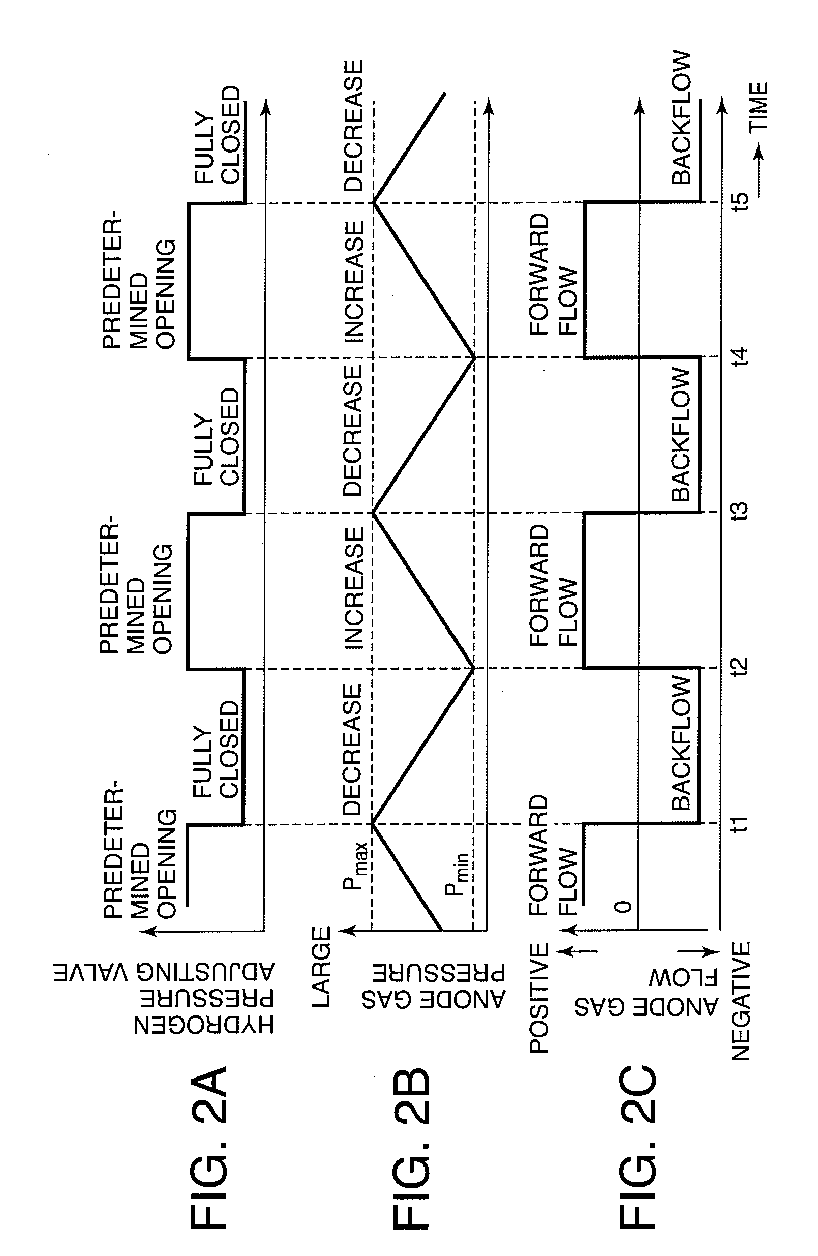
FIELD OF THE INVENTION[0001]This invention relates to operation control of a fuel cell power plant.BACKGROUND OF THE INVENTION[0002]JP2007-48479A, published by the Japan Patent Office in 2007, discloses an operation control device for a fuel cell power plant which performs a pressure pulsation operation on an anode gas. A pressure pulsation operation is an operation method in which an internal pressure of a fuel cell stack is caused to pulsate between an upper limit pressure and a lower limit pressure by halting an anode gas supply to the fuel cell stack when a pressure of the anode gas reaches the upper limit pressure and restarting the anode gas supply when the pressure of the anode gas falls to the lower limit pressure. With this prior art technique, it is possible to promote the discharge of water generated in the fuel cell stack along a pressure gradient formed as the pressure falls during the pressure pulsation operation.SUMMARY OF THE INVENTION[0003]According to research cond...

Claims


Application Information

Patent Timeline
Patent Type & Authority Applications(United States)
IPC IPC(8): H01M8/04
CPCH01M8/04388H01M8/04395H01M8/04447H01M8/04455H01M8/04559H01M8/04589H01M8/04619H01M8/04753H01M8/04798H01M8/0494H01M2008/1095Y02E60/50H01M8/04089
Inventor TOMITA, YOUSUKESATO, MASASHI
Owner NISSAN MOTOR CO LTD
Learn More