Antenna module

a technology of antenna module and antenna module, which is applied in the direction of antenna, polarised antenna unit combination, basic electric elements, etc., can solve the problems of antenna performance, the overall volume of the wireless transceiver is too large, and the wireless transceiver cannot meet the current demands of being light in weight and small in size, so as to reduce the complexity of the manufacturing process and reduce the volume of the antenna module.

Active Publication Date: 2012-05-03
LYNWAVE TECH
View PDF7 Cites 1 Cited by
  • Summary
  • Abstract
  • Description
  • Claims
  • Application Information

AI Technical Summary

Benefits of technology

[0017]Therefore, the efficacy of the disclosure is that the antenna module is designed as an integral structure, thus significantly reducing the volume of the antenna module, and reducing the complexity in the manufacturing process and the manufacturing cost.

Problems solved by technology

However, in actual application, the conventional external antenna module is so large in size that the overall volume of the wireless transceiver is too large.
This is to say, the wireless transceiver is so large that the wireless transceivers cannot meet the current demands of being light in weight and small in size.
Otherwise, if the antenna module is laid out on the circuit board of the wireless transceiver, the antenna performance cannot be optimized, and if there are several antenna modules, the problem that the volume occupied by the wireless transceiver is too large to meet the current demands that the electronic products must be light in weight and small in size.
On the contrary, in order to keep the wireless transceiver to be light in weight and small in size, the volume of the antenna module needs to be limited below a certain scale, so that the operation band of the antenna module is limited, and even a problem of poor stability of a radiation pattern is generated.

Method used


Image

  • Antenna module
  • Antenna module
  • Antenna module

Examples


first embodiment

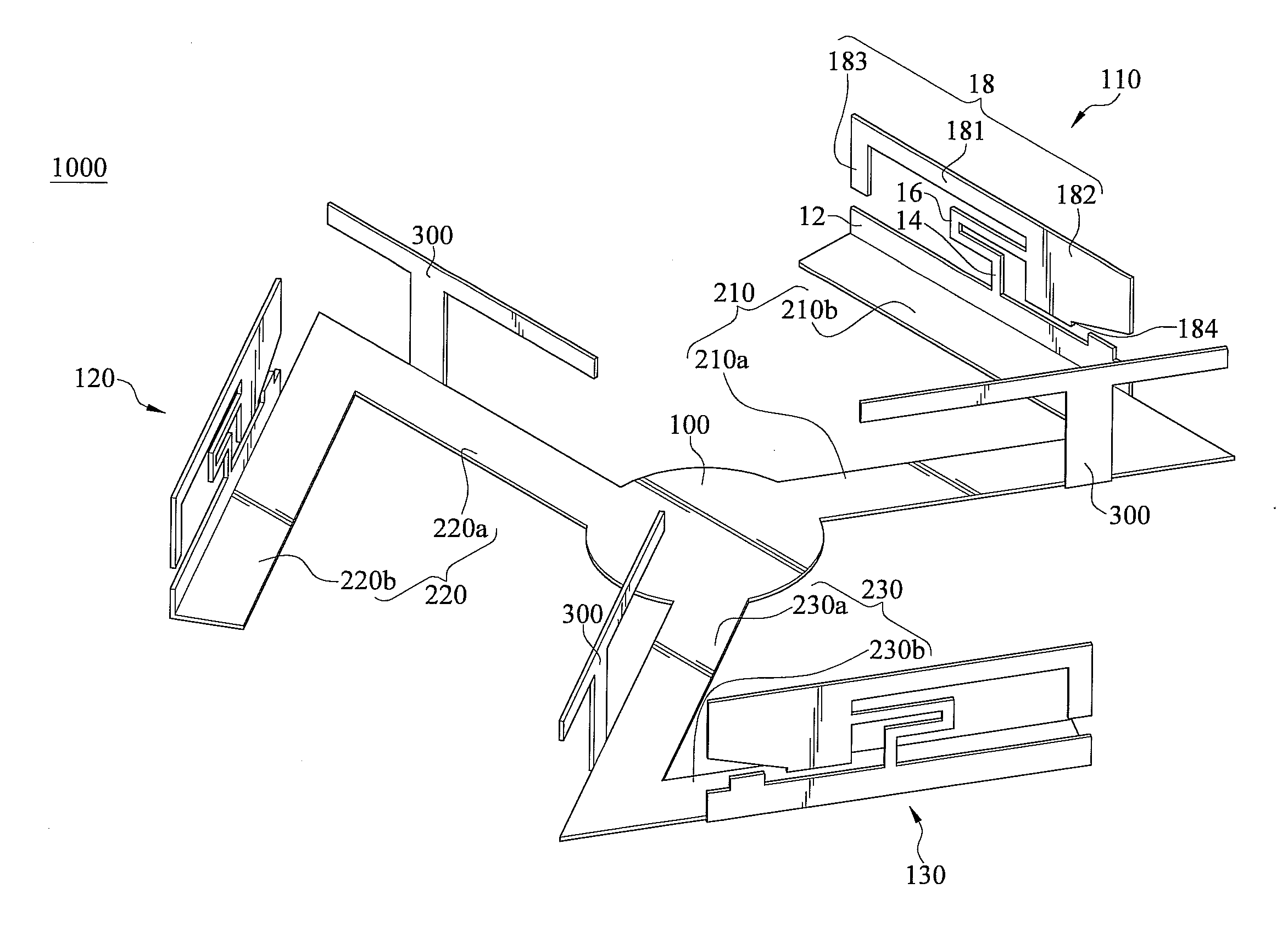
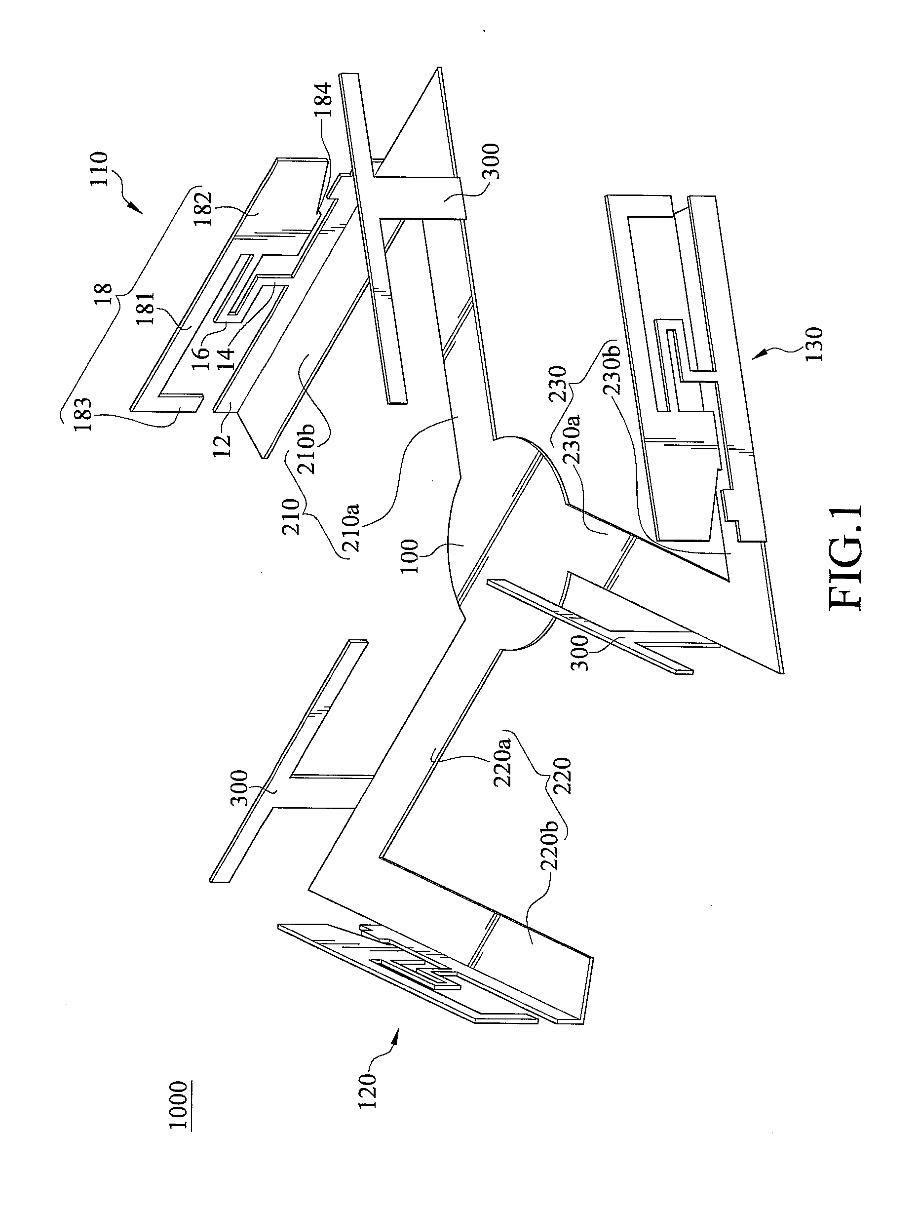
[0022]FIG. 1 is a schematic structural diagram of an antenna module according to the disclosure. The structure shown in FIG. 1 is formed by a single piece of conductive material, for example, a metal sheet. For the convenience of description, the antenna module is disassembled into multiple components for illustration.

[0023]The antenna module 1000 according to the first embodiment of the disclosure comprises a center base 100, a first antenna 110, a second antenna 120, and a third antenna 130. The center base 100 has a first extension leg 210, a second extension leg 220, and a third extension leg 230, which are formed by extending from the center base 100 respectively. The first extension leg 210, the second extension leg 220, and the third extension leg 230 are symmetrically arranged around the center base 100 and divide the perimeter of the center base 100 into equal parts.

[0024]The first extension leg 210 comprises a pair of a first extension portion 210a and a second extension p...

second embodiment

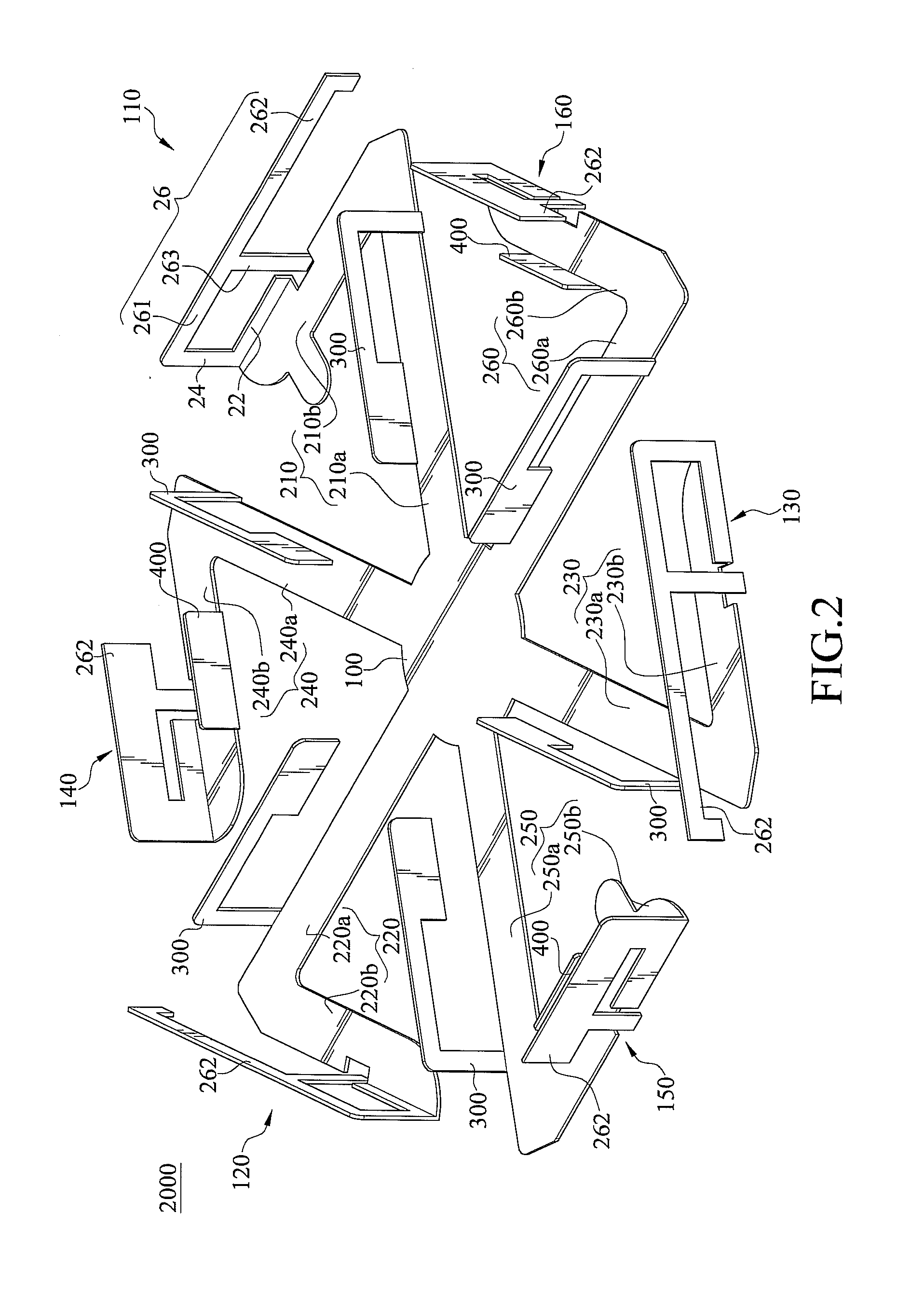
[0031]FIG. 2 is a schematic structural diagram of an antenna module according to the disclosure. The structure shown in FIG. 2 is formed from a single piece of conductive material, for example, a metal sheet. For the convenience of description, the antenna module is disassembled into multiple components for illustration.

[0032]The antenna module 2000 according to the second embodiment of the disclosure comprises a center base 100, a first antenna 110, a second antenna 120, a third antenna 130, a fourth antenna 140, a fifth antenna 150, and a sixth antenna 160. The center base 100 has a first extension leg 210, a second extension leg 220, a third extension leg 230, a fourth extension leg 240, a fifth extension leg 250, and a sixth extension leg 260, which are formed by extending from the center base 100 respectively. The first extension leg 210, the second extension leg 220, the third extension leg 230, the fourth extension leg 240, the fifth extension leg 250, and the sixth extension...


PUM


Abstract

An antenna module includes a center base and several antennas disposed around the center base. The center base has several extension legs extending from the center base, and each antenna extends from an end of the corresponding extension leg opposite to the center base, so as to form the antenna module symmetrically arranged around the center base. The type of the antenna may be a single-frequency antenna and a dual-frequency antenna. The antenna module is an integral structure formed by directly bending a single metal plate, thus greatly reducing the volume and the manufacturing cost of the antenna module. Moreover, with the design of the center base and a symmetrical antenna group, the antenna module is capable of receiving and transmitting signals with two or more frequency bands, thus greatly increasing the application range of the antenna module.

Description

CROSS-REFERENCE TO RELATED APPLICATIONS[0001]This non-provisional application claims priority under 35 U.S.C. §119(a) on Patent Application No(s). 099220795 filed in Taiwan, R.O.C. on Oct. 27, 2010, the entire contents of which are hereby incorporated by reference.BACKGROUND[0002]1. Technical Field[0003]The disclosure relates to an antenna module, and more particularly to an antenna module with several antennas symmetrically disposed around a center base.[0004]2. Related Art[0005]In recent years, with the popularization of consumer electronic products such as notebook computers and Personal Digital Assistants (PDA) and the rapid development of the Internet, information from different regions in the world is communicated and linked. Today, the interconnection architecture of the Internet is changed from a wired connection type such as using optical fibers, wires or cables, to a wireless connection type, so as to solve the problem that circuit layout of the network architecture of the...

Claims


Application Information

Patent Timeline
Patent Type & Authority Applications(United States)
IPC IPC(8): H01Q21/24H01Q21/30
CPCH01Q9/42H01Q21/30H01Q5/371
Inventor WU, SAN-YUAN
Owner LYNWAVE TECH
Why Eureka
Try Eureka