Eureka AIR delivers breakthrough ideas for toughest innovation challenges, trusted by R&D personnel around the world.

Bridge for a Stringed Musical Instrument

a musical instrument and bridge technology, applied in the field of bridges for stringed musical instruments, can solve the problems of improper frequency and brittle tones of metal bridges, and achieve the effect of maximizing the vibrations transmitted

Inactive Publication Date: 2012-05-03
LASHBROOK LARRY DAVID
View PDF34 Cites 16 Cited by
  • Summary
  • Abstract
  • Description
  • Claims
  • Application Information

AI Technical Summary

Benefits of technology

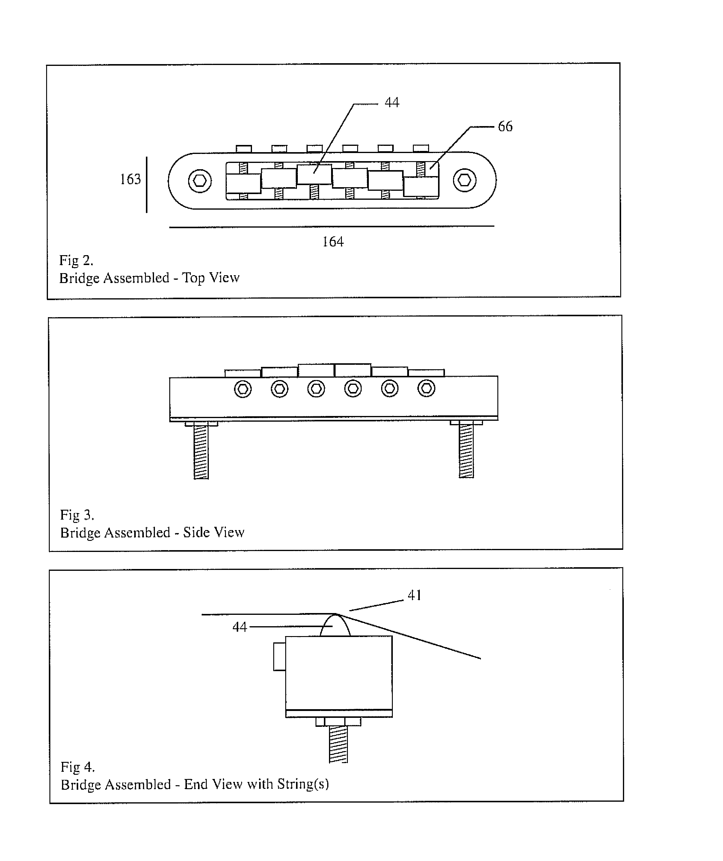
[0046]The constant contacts between adjacent saddles, between saddles and the end walls of the first chamber, and between saddles and the internal bottom wall of the first chamber collectively create a compressive load-bearing structure allowing for the bridge to be made of light-weight acoustically resonant materials, and allowing for the bridge to comprise wall structures including the primary diaphragm and the secondary diaphragm. The compressive load-bearing structure unifies the plurality of parts and maximizes the vibrations transmitted.
[0047]It is also an object of the present invention to provide a bridge for a musical instrument comprising a transverse axis and a longitudinal axis, the bridge having at least one hole oriented vertically in the bridge with a mounting member positioned within the hole, wherein the bridge is made of light-weight acoustically resonant material. The bridge may further comprise a first chamber wherein at least one saddle is positioned within the first chamber. The bridge may comprise a second chamber wherein at least one piezoelectric element is positioned within the second chamber. The mounting member can be used to adjust the height of the bridge.

Problems solved by technology

In addition, the piezoelectric bridge allows the electric guitar to produce sounds at high volume without feedback, a drawback normally associated with acoustic guitars.
However, the metal bridge produces a low output signal with improper frequencies and brittle tones.

Method used


Image

  • Bridge for a Stringed Musical Instrument
  • Bridge for a Stringed Musical Instrument
  • Bridge for a Stringed Musical Instrument

Examples


Embodiment Construction

[0048]The present invention provides a bridge for a stringed instrument with structure design that allows the bridge to be made of comparatively light-weight, acoustically resonant material. The comparatively light-weight, acoustically resonant material is described more fully below. The bridge contains a plurality of adjustable saddles. The adjacent saddles are always in direct contact. Each saddle is always in contact with the internal bottom wall of the first chamber of the bridge. The saddles that are positioned at either end of the plurality of saddles are always in direct contact with the end walls of the first chamber. The compressive load provided by these constant contacts enables the instant bridge to withstand even the heaviest load of strings. The constant contacts between the saddles, and between the saddles and the walls of the first chamber of the bridge, also enable these plurality of parts to be unified by pressure allowing for excellent transmission of the string v...


PUM


Abstract

The present invention provides a bridge for a stringed instrument with improved structure design which allows the bridge to be made of light-weight acoustically resonant material. The bridge comprises a plurality of adjustable saddles that are always in contact with the adjacent saddles, the internal bottom wall, and / or the end walls of the first chamber of the bridge. The constant contacts enable these plurality of parts to be unified by pressure allowing for excellent transmission of the string vibrations. The compressive load provided by these constant contacts enables the instant bridge to withstand even the heaviest load of strings. In addition, the bridge comprises thin walls facilitating resonance. The bridge may also comprise internal piezoelectric elements. The bridge is able to produce authentic acoustic sounds for an electric guitar without the need for pre-amplification or signal conditioning.

Description

CROSS REFERENCE TO RELATED APPLICATIONS[0001]This application claims the benefit under 35 U.S.C. §119(e) of U.S. Provisional Application No. 61 / 109,002, filed on Oct. 28, 2008.FIELD OF THE INVENTION[0002]The present invention relates to bridges for stringed musical instruments. In particular, the present invention relates to bridges for guitars.BACKGROUND OF THE INVENTION[0003]On a stringed musical instrument, a bridge is a device for supporting the strings and transmitting the vibration of the strings to other structural components of the instrument to maximize intensity of the sound. A pickup can be part of the bridge assembly which acts as a transducer to convert mechanical vibrations of the strings to electrical signals. An amplifier system then receives and amplifies the electric signals for acoustic emission. In general, an electric guitar has a magnetic pickup which converts string vibrations inside a magnetic field to electric currents. An acoustic guitar typically has a pie...

Claims


Application Information

Patent Timeline
IPC IPC(8): G10D3/04G10H3/18
CPCG10D3/04
Inventor LASHBROOK, LARRY DAVID
Owner LASHBROOK LARRY DAVID
Why Eureka
Eureka Blog
Learn More