
Catheter patch applicator assembly

a technology for applicators and catheters, applied in the field of catheter patch applicators, can solve the problems of increasing the likelihood of hands and/or fingers contaminating the sterilized patch itself or the iv site, and the possibility of foreign contamination of the insertion site via the fingers and hands of a technician or medical provider

Active Publication Date: 2012-04-26
CAREFUSION 2200 INC
View PDF13 Cites 5 Cited by
  • Summary
  • Abstract
  • Description
  • Claims
  • Application Information

AI Technical Summary

Benefits of technology

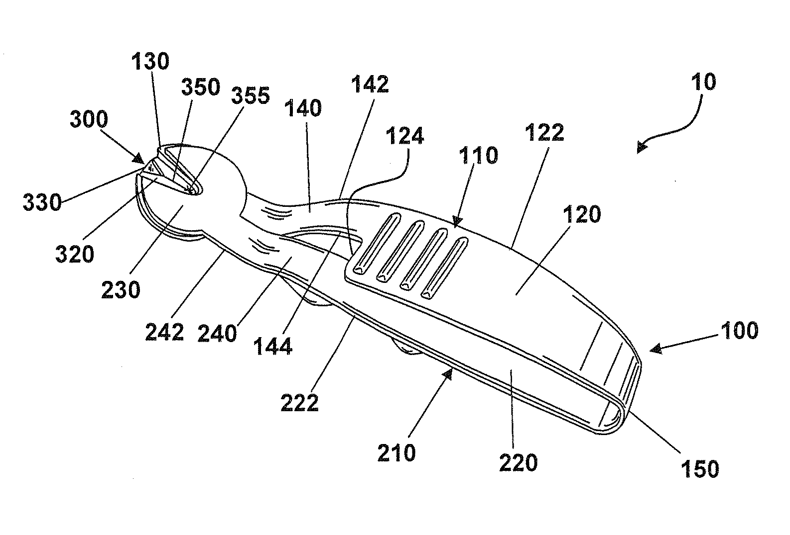
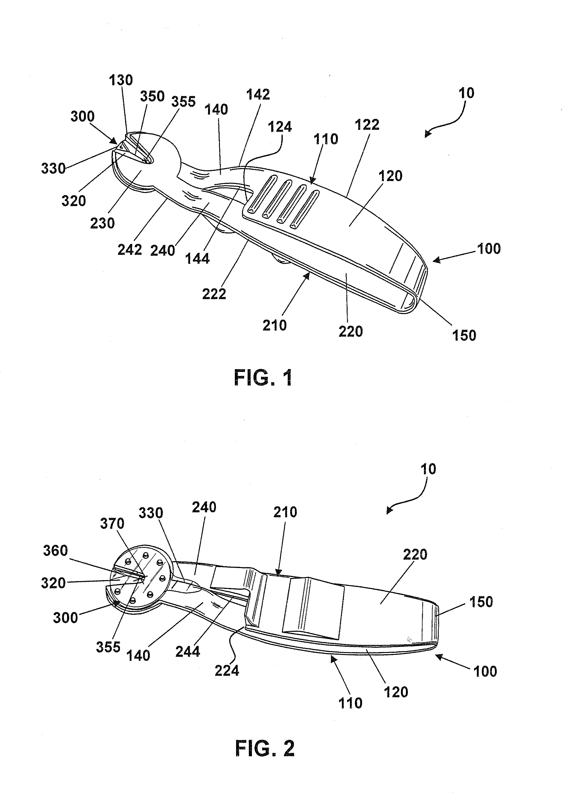
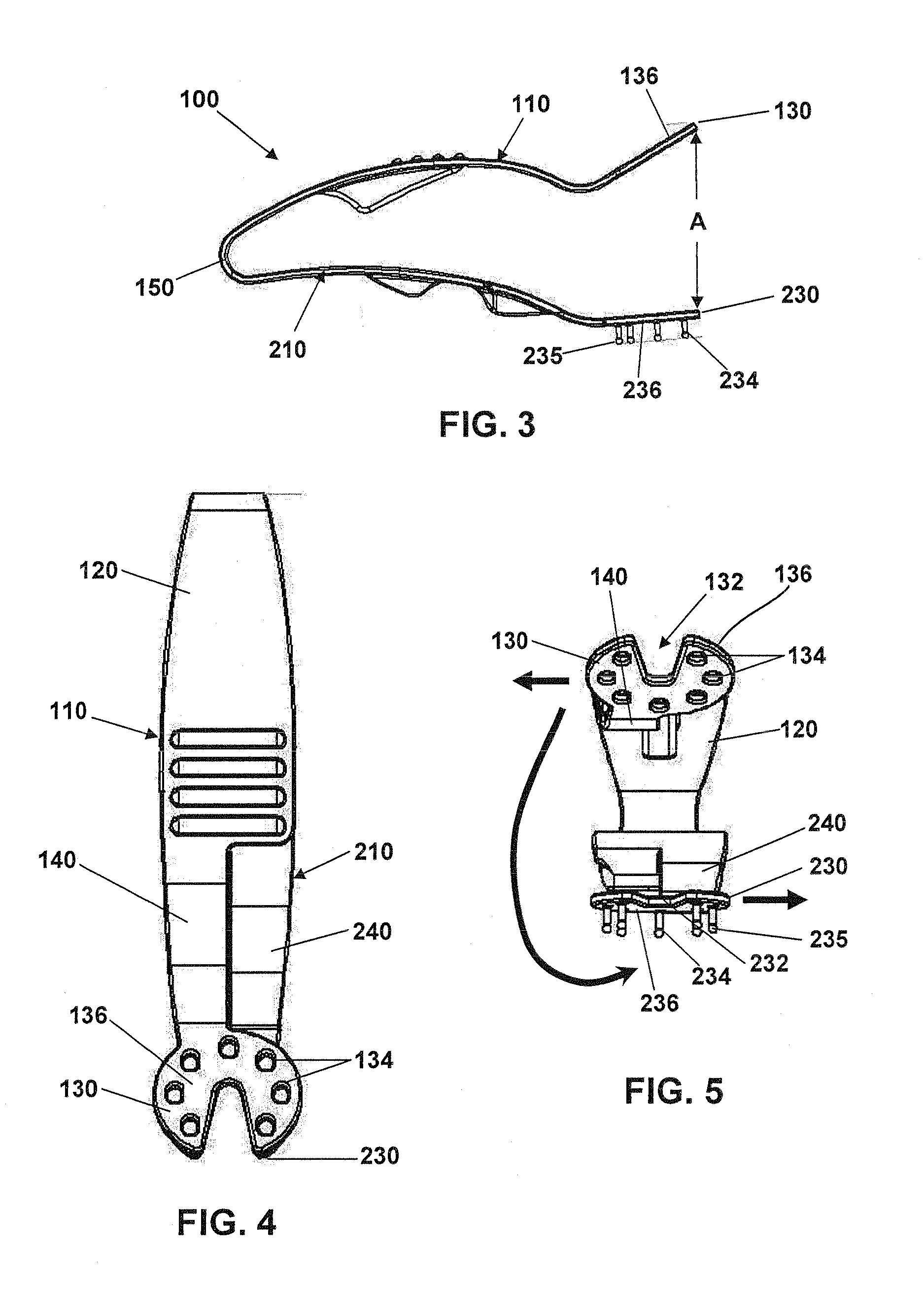
The present invention is about a catheter patch and applicator assembly for easy and one-handed application. The applicator assembly includes an upper arm and a lower arm with a hinge member, and a tacky layer is secured to the lower arm. The assembly is designed to be secured against the lower arm and can be easily applied to the insertion site of a percutaneous device. The technical effects of the invention include easy and convenient application of a catheter patch with one hand, and improved stability and securement of the patch during use.

Problems solved by technology

Each time a dressing is applied to stabilize or protect the insertion site, there exists an opportunity for foreign contamination of the insertion site via the fingers and hands of a technician or medical provider, for example.
Unfortunately, the manner in which dressings or patches of the related art are designed and / or applied often requires the use of both hands to hold and apply a dressing to a catheter site, or the placement of fingers near the insertion site to hold and / or apply the dressing or patch.
This significantly increases the likelihood of contamination of a sterilized IV site or the sterilized patch itself by the hands and / or fingers.

Method used


Image

  • Catheter patch applicator assembly
  • Catheter patch applicator assembly
  • Catheter patch applicator assembly

Examples


Embodiment Construction

[0031]Various aspects of a catheter patch and applicator assembly may be illustrated by describing components that are coupled, attached, and / or joined together. As used herein, the terms “coupled”, “attached”, and / or “joined” are used to indicate either a direct connection between two components or, where appropriate, an indirect connection to one another through intervening or intermediate components. In contrast, when a component is referred to as being “directly coupled”, “directly attached”, and / or “directly joined” to another component, there are no intervening elements present.

[0032]Relative terms such as “lower” or “bottom” and “upper” or “top” may be used herein to describe one element's relationship to another element illustrated in the drawings. It will be understood that relative terms are intended to encompass different orientations of a catheter patch and applicator assembly in addition to the orientation depicted in the drawings. By way of example, if a catheter patch...


PUM


Abstract

In accordance with aspects of the present invention, an applicator assembly suitable for application of a catheter patch with one hand comprises an upper arm with a proximal end and a distal portion, a lower arm with a proximal end and a distal portion, and a hinge member fixedly joining the proximal ends of the upper arm and the lower arm, wherein an upper surface of the upper arm distal portion abuts a lower surface of the lower arm distal portion. In accordance with another aspect of the present invention, a catheter patch assembly may be secured against a lower surface of the upper arm distal portion. The distal portion of the lower arm may include a securing mechanism for securing the catheter patch assembly to the applicator assembly. A method of applying a catheter patch is provided.

Description

BACKGROUND[0001]1. Field[0002]The present disclosure relates to a catheter patch applicator assembly and method of use thereof, and more particularly, to a catheter patch applicator assembly that permits single-hand sterile application of a catheter patch to a patient's skin for lubricating catheters, as surgical dressings, and / or as wound dressings.[0003]2. Description of Related Art[0004]Surgical dressings, wound dressings, and catheter-securing patches for use with catheters or other percutaneous devices, such as feeding tubes, orthopedic fixation pins, or electrical leads, for example, are common in the prior art. The primary concern with transdermal access into the body is the prevention of infection and irritation to the insertion site of the percutaneous device.[0005]For example, long-term care and vascular access catheters are increasingly used to provide indefinite access to a patient's blood vessels for drawing blood or administering medication. The placement of a catheter...

Claims


Application Information

Patent Timeline
Patent Type & Authority Applications(United States)
IPC IPC(8): A61B17/00
CPCA61M2025/0273A61B17/00A61F15/005
Inventor FLORES, JESUSTUFTS, SCOTT
Owner CAREFUSION 2200 INC
Learn More