Endoscope overtube

a flexible endoscope and overtube technology, applied in the field of endoscope overtube, can solve the problems of inability to perform easy and appropriately, operation that requires lateral movement rather than axial movement of the operation of applying tension (traction) to the tissue to be treated, so as to improve the operability and improve the safety of medical care.

Inactive Publication Date: 2012-04-19
OSAKA UNIV
View PDF14 Cites 17 Cited by
  • Summary
  • Abstract
  • Description
  • Claims
  • Application Information

AI Technical Summary

Benefits of technology

[0018]The endoscope overtube of the present invention is characterized in that (1) a treatment instrument insertion passage is provided in the wall of an already-existing endoscope overtube and that (2) the treatment instrument insertion passage of the overtube extends preferably in a helical direction, rather than a direction along the major axis of the overtube. Accordingly, the treatment instrument is protruded from the distal end of the overtube in a direction different from that of the center of a surgical field, and extends outward, away from a direction along the viewing axis of the overtube. For example, when the treatment instrument inserted into the insertion passage

Problems solved by technology

Such maneuvers using a flexible endoscope and an overtube that are currently available have some technological problems.
Consequently, operations that require a sufficient distance between the surgical site and the treatment instrument and operations that require lateral movement rather than movement in the axial direction, including, for example, the operation of applying tension (traction) to a tissue to be treated, cannot be performed easily and appropriately.
Also for a multichannel endoscope provided with two or more channel

Method used


Image

  • Endoscope overtube
  • Endoscope overtube
  • Endoscope overtube

Examples


examples

[0042]Hereinafter, the present invention will be described in detail with reference to the drawings.

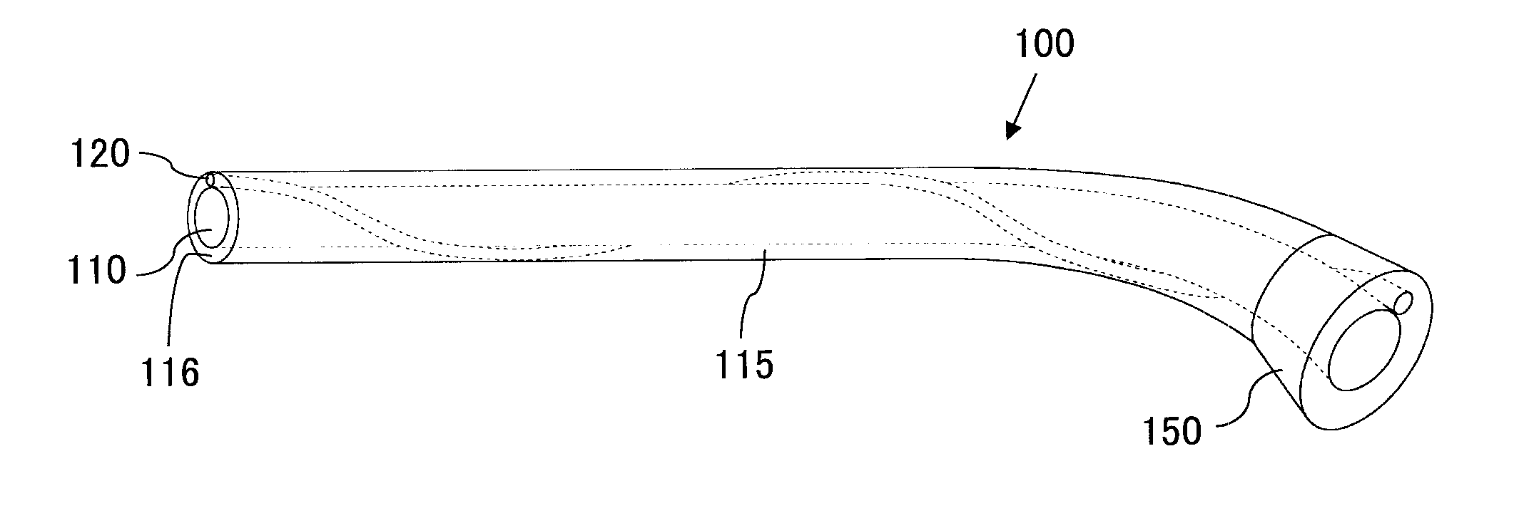
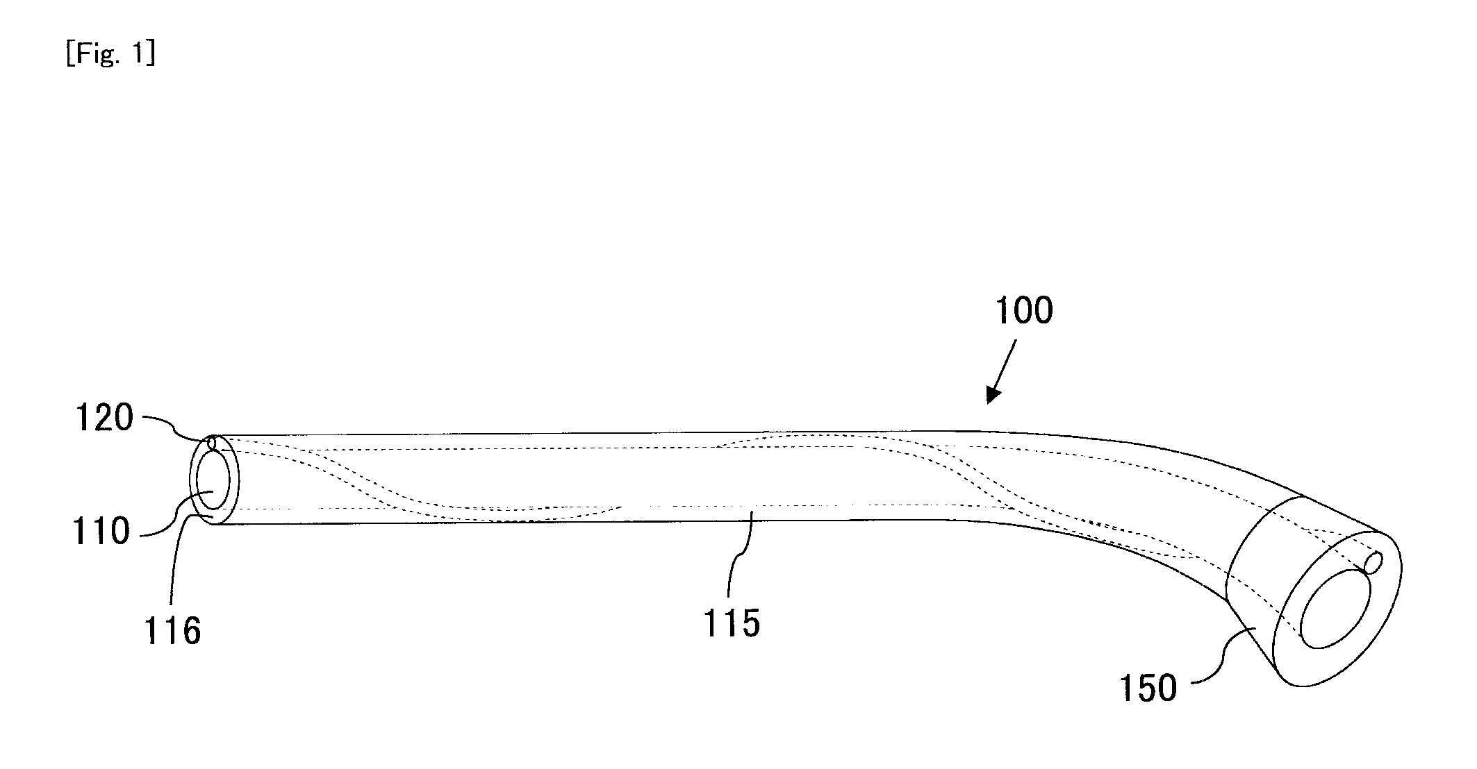
[0043]FIG. 1 shows a schematic diagram showing the structure of an endoscope overtube 100 according to the present invention. The endoscope overtube 100 of the present invention includes a first insertion passage 110 into which an endoscope 200 (not shown) is inserted, and a second insertion passage 120 into which a treatment instrument 300 (not shown) is inserted is provided in the form of a helix in a wall 115 constituting the first insertion passage 110. The helix has a pitch of two turns (720°) throughout the entire length of the second insertion passage. The major axis direction of the second insertion passage 120 is different from the major axis direction of the first insertion passage 110 at the distal end of the second insertion passage 120. The proximal end side of the overtube 100 is provided with a base end portion 150 made of a resin that is harder than the flexible resin ...


PUM


Abstract

An object of the present invention is to provide means capable of steering a treatment instrument together with an endoscope with good operability in endoscopic surgery. The endoscope overtube of the present invention includes a first insertion passage into which an endoscope is inserted, wherein a wall constituting the first insertion passage includes a second insertion passage into which a treatment instrument is inserted, and a major axis direction of the second insertion passage is different from a major axis direction of the first insertion passage at a distal end of the second insertion passage. Since the treatment instrument insertion passage of the overtube does not extend in a direction along the major axis of the overtube, the treatment instrument is protruded from the distal end of the overtube in a direction different from that of the center of a surgical field, and extends outward, away from a direction along the viewing axis of the overtube. For example, when a grasping forceps is inserted into the insertion passage of the overtube, by adjusting the extent of protrusion of the grasping forceps, it is possible to grip a tissue under an appropriate tension and perform a treatment such as removal with a treatment instrument such as an electrocautery inserted from the treatment instrument channel of the endoscope.

Description

TECHNICAL FIELD[0001]The present invention relates to an endoscope overtube. More particularly, the invention relates to an overtube that enables a treatment instrument to be protruded in a direction different from the viewing axis of an endoscope with good operability.BACKGROUND ART[0002]In general, an endoscope is provided, at its tip portion, with an observation optical system, an illumination optical system for illuminating an affected area, an air supply and water supply channel, a treatment instrument channel, and so forth. By introducing a treatment instrument such as a forceps from the treatment instrument channel while using an endoscope to observe an affected area in a lumen such as stomach from a video camera portion, it is possible to perform various maneuvers such as specimen retrieval, removal of a foreign body, hemostasis, resection of a tumor, and gallstone. Overtubes for assisting insertion of an endoscope or for simultaneous insertion of a plurality of endoscopes o...

Claims


Application Information

Patent Timeline
IPC IPC(8): A61B1/00
CPCA61B1/00135A61B2017/00296A61B1/018A61B2017/00269A61B2017/3445
Inventor NAKAJIMA, KIYOKAZU
Owner OSAKA UNIV
Why Eureka
Try Eureka