
Variable speed switch and electric power tool with the variable speed switch mounted thereto

a variable speed switch and electric power tool technology, which is applied in the direction of dynamo-electric machines, pump control, fluid engines with non-positive displacement, etc., can solve the problems of complicated waterproof structure of electric power tools with the variable speed switch b>100/b> attached thereto, and simplify the waterproof structure of electric power tools. , the effect of improving the degree of freedom of mounting

Active Publication Date: 2012-03-22
MAKITA CORP
View PDF10 Cites 34 Cited by
  • Summary
  • Abstract
  • Description
  • Claims
  • Application Information

AI Technical Summary

Benefits of technology

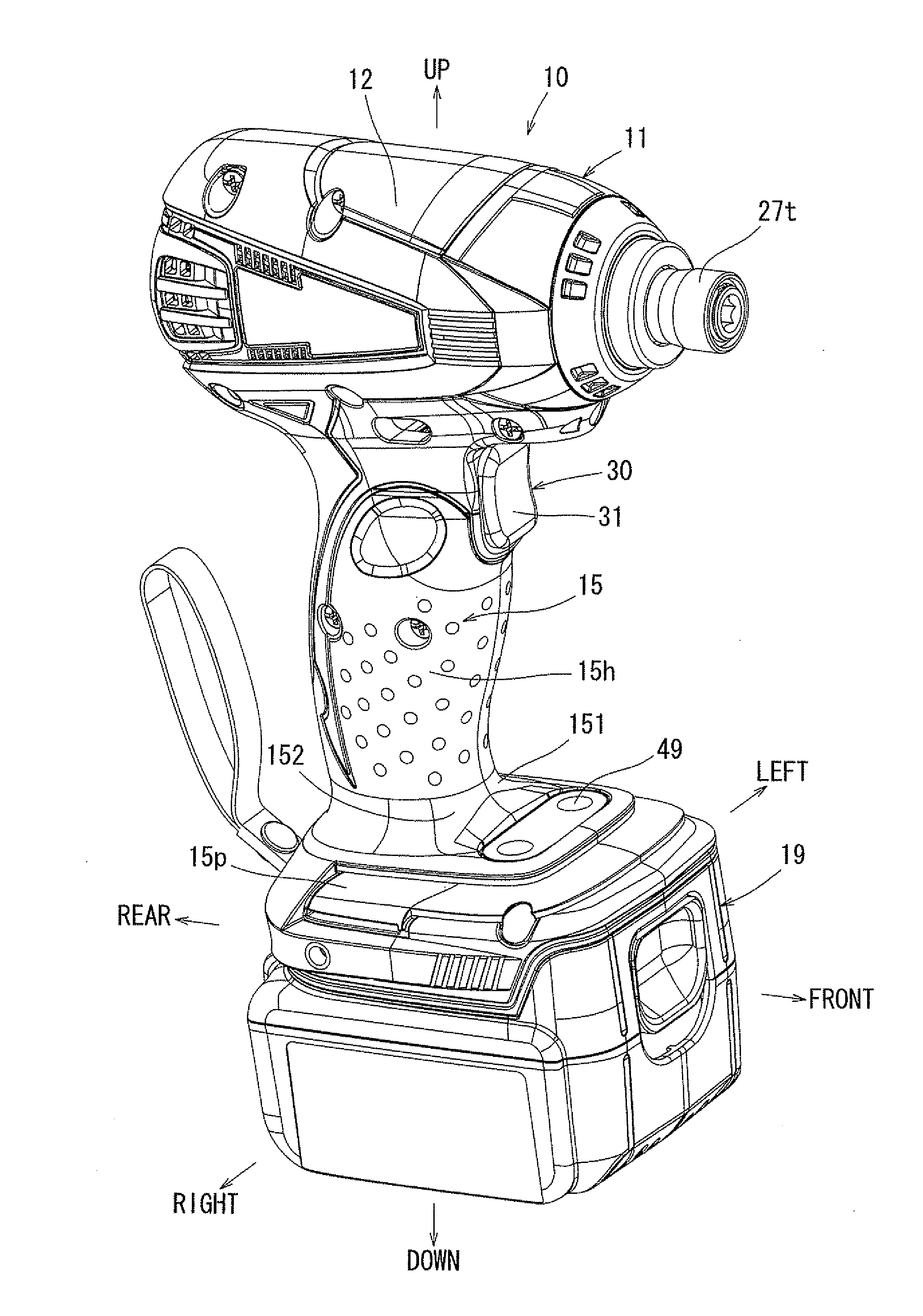
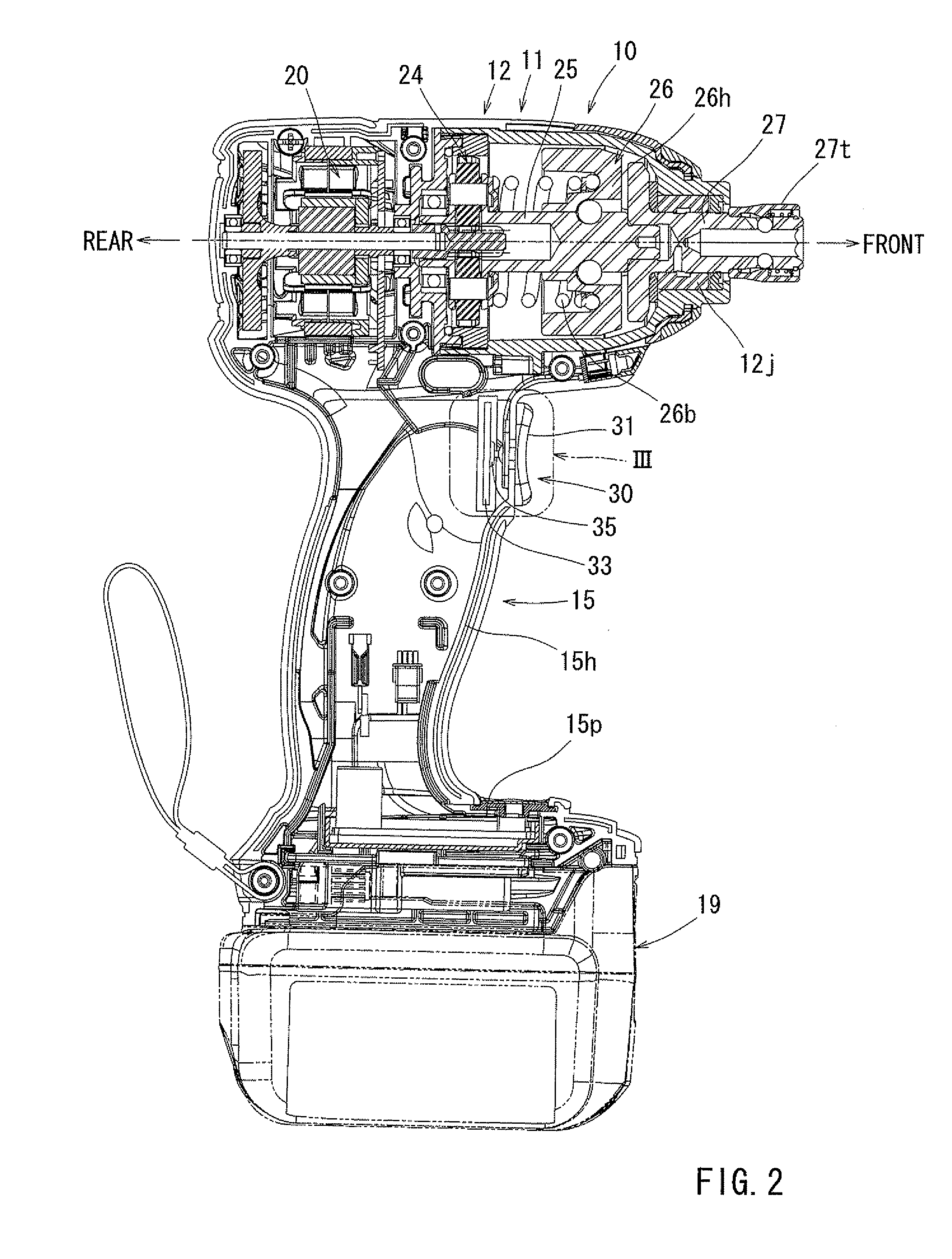
The patent describes a variable speed switch for an electric power tool that can adjust the amount of electric power supplied to the motor by the amount of displacement of the switch operating portion. The switch operating portion is mounted on the housing of the electric power tool and can transmit a pressing force to a load sensor inside the housing. The load sensor converts the amount of distortion caused by the pressing force into an electric signal. The maximum displacement amount of the switch operating portion is set to be equal to or less than 5 mm, which allows for a smaller size of the switch and improved flexibility in its positioning. The housing of the electric power tool can include a tubular housing main body and a handle portion radially protruding from the housing main body, which reduces the stroke of the trigger of the variable speed switch. The switch operating portion can be made of an elastic material to seal the opening of the housing. The electric power tool can also have a wake-up switch that is independent of the variable speed switch and can start up the control circuit of the motor before the variable speed switch is pulled. This simplifies the waterproof structure of the electric power tool and reduces the cost.

Problems solved by technology

Further, since the stroke of the trigger 102 with respect to the switch main body 105 is relatively large, the waterproof structure for the electric power tool with the variable speed switch 100 attached thereto may be rather complicated.

Method used


Image

  • Variable speed switch and electric power tool with the variable speed switch mounted thereto
  • Variable speed switch and electric power tool with the variable speed switch mounted thereto
  • Variable speed switch and electric power tool with the variable speed switch mounted thereto

Examples


Embodiment Construction

[0047]Each of the additional features and teachings disclosed above and below may be utilized separately or in conjunction with other features and teachings to provide improved variable speed switch. Representative examples of the present teaching, which examples utilize many of these additional features and teachings both separately and in conjunction with one another, will now be described in detail with reference to the attached drawings. This detailed description is merely intended to teach a person of skill in the art further details for practicing preferred aspects of the present teachings and is not intended to limit the scope of the invention. Only the claims define the scope of the claimed invention. Therefore, combinations of features and steps disclosed in the following detailed description may not be necessary to practice the invention in the broadest sense, and are instead taught merely to particularly describe representative examples of the invention. Moreover, various...


PUM


Abstract

A variable speed switch includes a switch main body portion which is accommodated in a housing of an electric power tool and mounted to the housing so as to be capable of relative movement, and a load sensor which is provided in the switch main body portion and capable of outputting an electric signal in proportion to the amount of distortion caused by a pressing force. The switch operating portion is mounted on the surface of the housing so as to be capable of relative displacement with respect to the housing and transmits a pressing force applied to the switch operating portion to the load sensor, with the maximum displacement amount of the switch operating portion being set to equal to or less than 5 mm.

Description

[0001]This application claims priority to Japanese patent application serial numbers 2010-209130 and 2010-226365, the contents of which are incorporated herein by references.BACKGROUND OF THE INVENTION[0002]1. Field of the Invention[0003]The present invention relates to a variable speed switch which is mounted to an electric power tool etc. and capable of outputting an electric signal for increasing and decreasing the amount of an electric power supplied to a motor of the electric power tool in proportion to the displacement amount of a switch operating portion. The present invention further relates to an electric power tool provided with the above variable speed switch and further provided with a wake-up switch configured to apply voltage to a control circuit of the motor to work the control circuit.[0004]2. Description of the Related Art[0005]Japanese Patent Application Laid-Open No. 2003-260675 discloses a variable speed switch in the prior art.[0006]As shown in FIG. 12, a variab...

Claims


Application Information

Patent Timeline
Patent Type & Authority Applications(United States)
IPC IPC(8): H02K7/14
CPCB25F5/001B25F5/02H02K7/14H01H9/061H01H2009/048H01H9/04
Inventor WATANABE, MASAHIROKUSAKAWA, TAKUYANAGASAKA, HIDENORI
Owner MAKITA CORP
Learn More