
Positive Airway Pressure System and Method

a pressure system and airway technology, applied in the field of positive airway pressure devices and methods, can solve the problems of hypopnea or apnea event, pharynx collapse, and related art cpap masks that do not maintain a constant leakage rate for different pressures, and achieve the effect of improving patient therapy

Inactive Publication Date: 2012-03-15
CARRILLO JR OSCAR +1
View PDF7 Cites 107 Cited by
  • Summary
  • Abstract
  • Description
  • Claims
  • Application Information

AI Technical Summary

Benefits of technology

"The patent is about a system and method for controlling the release of gases from a patient's circuit during a CPAP therapy. The system can adjust the speed of the blower and the amount of released gases to improve patient therapy. It also includes methods for controlling patient CO2 retention and measuring patient metabolic function. The technical effects of this patent are improved patient therapy and better control over the release of gases during CPAP therapy."

Problems solved by technology

In particular, in some patients the pharynx may collapse due to forces of gravity and / or due to forces associated with lower pressure in the upper airway relative to the pressure on the outer wall of the pharynx.
A collapse of the pharynx, larynx, upper airway or other soft tissue in the respiratory tract may thus cause the full or partial blockage, which may lead to a hypopnea or apnea event.
Related art CPAP masks do not maintain a constant leak rate for different pressures.
The misinterpretation may lead to false detection, or measurement, of patient breathing which may lead to improper pressure corrections by related art CPAP systems.
However, these algorithmic mechanisms are relatively insensitive, requiring a substantial mask leak before the algorithm can conclusively determine that a mask leak is present.
Moreover, these algorithmic determinations are prone to false indications of a mask leak when in actuality the air escape may be through the mouth, mouth leak.
Since mask pressure changes the amount of vent leak, it becomes increasing difficult to assess and quantify the differences between a mask leak and the intentional vent leak, which may lead to false or inaccurate CPAP device response to such a measurement.
The intentional release of gases from related art CPAP masks create a highly undesirable audible noise of escaping gases which often interrupts patient and / or bed partner sleep.
Devices common in the art make attempts to dampen the noises generated by the vent leak but patients and bed partners still complain of this noise and of sleep interruption caused by this noise.
The intentional release of gases from related art CPAP masks create a highly undesirable alteration of audible noises that are in synchrony with the patient's breathing.
The patient may focus on the breathing noises and lead to an inability to initiate sleep.
The intentional release of gases from related art CPAP masks create airflows that often blow onto the patient and / or bed partners, which often interrupts patient's and / or bed partner's sleep.
Devices common in the art make attempts to dampen the airflows from the vent leak but patients and bed partners still complain of the airflow annoyances and of sleep interruption cause by this airflow.
This often results from the high flow of gases escaping from the vent port in the patient mask.
This may lead to CPAP induced central apneas for the patient.
This situation is worsened at higher operating pressures since gases escape at a greater rate from the fixed geometry vent port.
High titration pressures can lead to hypoventilating the patient and / or patient discomfort.
Because of the aforementioned pressure swings at the mask, accurate pressure measurements and control of pressure remotely from the patient mask in the CPAP device is inadequate and imprecise.
Unnecessarily high CPAP pressures lower patient compliance to the prescribed therapy.
As a result of these factors, related art CPAP machines may be unable to detect cardioballistic data when, in fact, the signal is present.
Related art CPAP machines are only able to detect cardioballistic data when breathing is absent.

Method used


Image

  • Positive Airway Pressure System and Method
  • Positive Airway Pressure System and Method
  • Positive Airway Pressure System and Method

Examples


Embodiment Construction

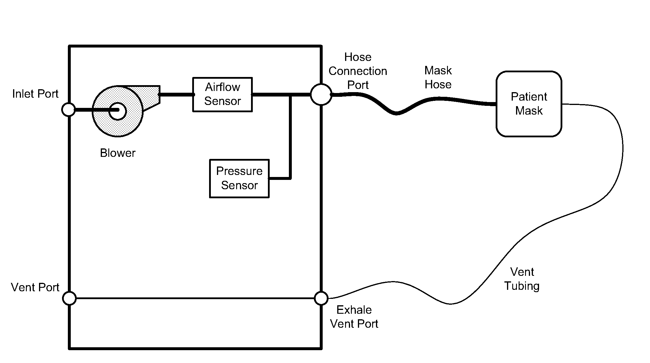
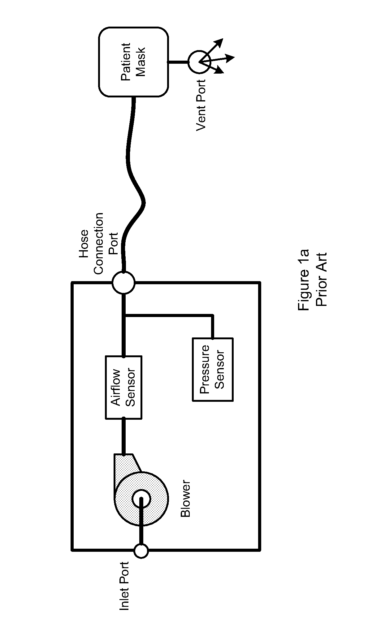
[0036]A common prior art device is disclosed in FIG. 1a. Airflow is generated by the blower. Air enters the inlet port and is fed to the blower. Generated airflow is delivered from the blower, through the airflow sensor, and exits the device at the hose connection port, through the patient hose, to the patient mask, and to the patient. A vent port is provided at the mask to expel CO2. The mask typically fits over the patient's nose but may enclose the patient's nose and mouth. Airflow and / or pressures are measured and controlled within the device shown.

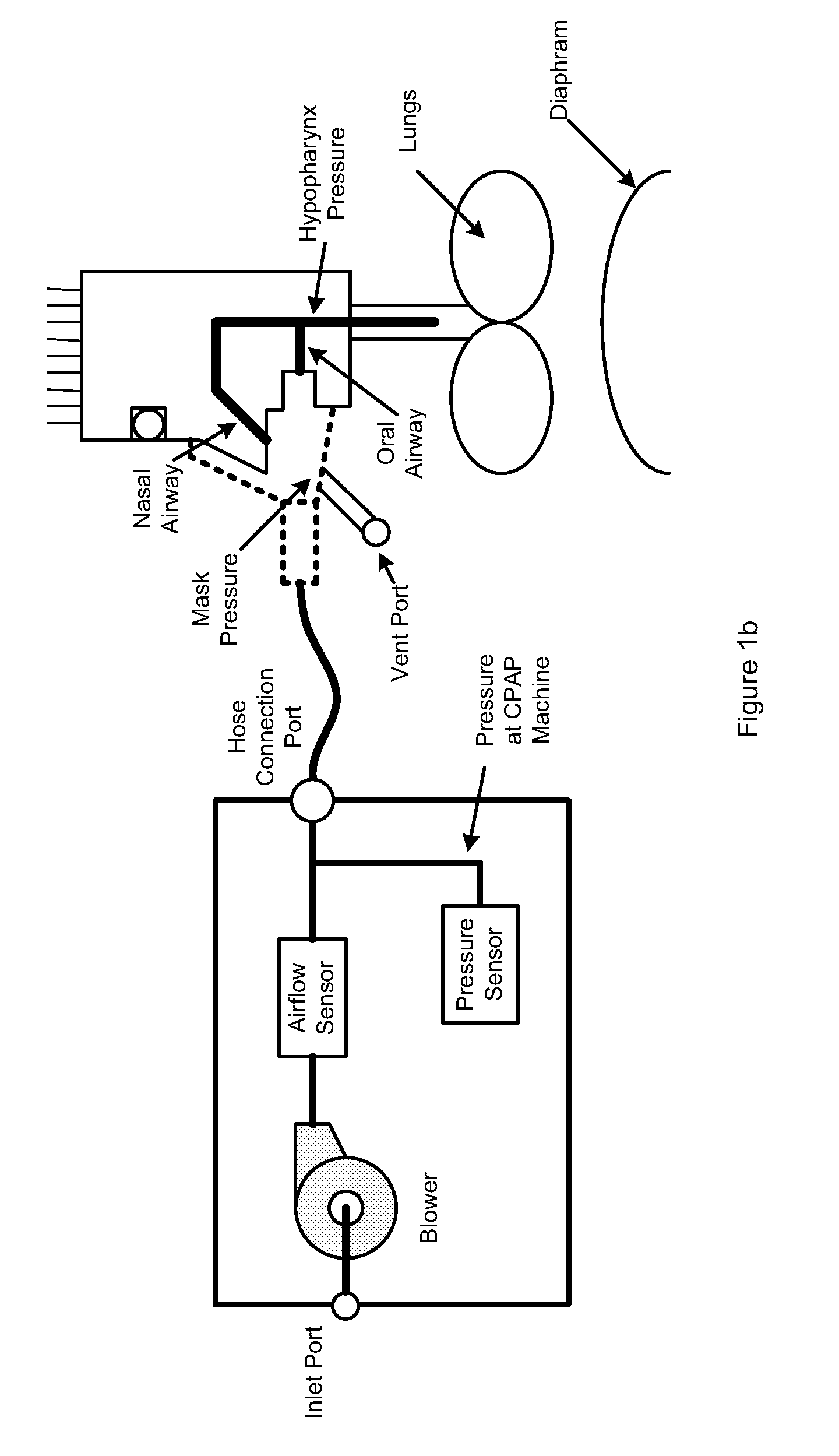
[0037]Refer to FIG. 1b. Pressure and fluctuations in pressure at any location in the CPAP circuit is determined by the distance from the device and the vent port. In prior art, the vent port is placed in the mask. Rapoport's APSS 2007 Abstract # 0080 abstract shows that therapeutic pressure at the hypopharynx can be drastically different than the mask pressure.

[0038]Referring to FIG. 2a, at least one preferred embodiment of the propos...


PUM


Abstract

A CPAP system and method which allows the control of released gases from the patient circuit. Coordination of blower speeds and the amount of released gases to improve patient therapy are disclosed. Methods and systems to control patient CO2 retention within the patient mask and to measure patient metabolic function are disclosed.

Description

CROSS-REFERENCE TO RELATED APPLICATIONS[0001]This non-provisional application claims priority based upon prior U.S. Provisional Patent Application No. 61349249 filed May 28, 2010 in the name of Oscar Carrillo, Jr and Alonzo C. Aylsworth entitled “Positive Airway Pressure System and Method” the disclosure of which is incorporated herein in its entirety by reference.STATEMENT REGARDING FEDERALY SPONSORED RESEARCH OR DEVELOPMENT[0002]Not ApplicableREFERENCE TO SEQUENCY LISTING, A TABLE, OR A COMPUTER PROGRAM LISTING COMPACT DISC APPENDEX[0003]Not ApplicableFIELD OF THE INVENTION[0004]Embodiments of the present invention is directed to positive airway pressure devices and methods, for example continuous positive airway pressure (CPAP) devices. More particularly, some embodiments of the invention are directed to positive airway pressure devices and methods where the flow and / or pressure to and from the patient are controlled. Additionally, patient metabolism is monitored and system press...

Claims


Application Information

Patent Timeline
Patent Type & Authority Applications(United States)
IPC IPC(8): A61M16/06A61M16/20A61M16/00A61B5/083
CPCA61B5/083A61M16/205A61M16/0045A61M16/0051A61M2016/0027A61M2016/0039A61M2016/0042A61M2016/1025A61M2016/103A61M2205/15A61M2230/005A61M2230/432A61M2230/435A61M16/0069A61M16/161A61M16/00A61M16/085A61M16/0858A61M16/024
Inventor CARRILLO, JR., OSCARAYLSWORTH, ALONZO CHARLES
Owner CARRILLO JR OSCAR
Learn More