
Method, Device and Computer Program Product for Monitoring Patients Receiving Care

a patient and computer program technology, applied in the field of patient monitoring, can solve the problems of inflexible care processes, difficulty for clinicians to grasp the connection between multiple monitors, and difficulty in using multiple monitors

Inactive Publication Date: 2012-03-01
GENERAL ELECTRIC CO
View PDF17 Cites 14 Cited by
  • Summary
  • Abstract
  • Description
  • Claims
  • Application Information

AI Technical Summary

Benefits of technology

[0005]The above-mentioned problems are addressed herein which will be comprehended from the following specification. The monitoring mechanism disclosed is based on a discovery that at a higher level of abstraction, many care processes obey similar logic and can thus be modified from the same generic monitor template, if certain prerequisites are taken into account in the template, such as the need to track the ability of the subject to receive care according to a certain care phase. This generic monitor template then allows creation of a set of different clinical applications having visually informative user interfaces that are similar to each other regardless of the different applications.

Problems solved by technology

Although this provides substantial support for the medical staff in view of the diseases or medical conditions concerned, it also makes the care processes inflexible since the built-in intelligence of one monitor / system is for the specific medical condition only and cannot be adapted to other medical conditions.
Furthermore, as each monitor / system is designed for a specific medical condition, the use of multiple monitors is normally challenging, due to the different human-machine interfaces.
Due to the complexity of the built-in intelligence, it may also be difficult for a clinician to grasp the connection between the behavior of the clinical index displayed by the system and the underlying physiological behavior of the patient.

Method used


Image

  • Method, Device and Computer Program Product for Monitoring Patients Receiving Care
  • Method, Device and Computer Program Product for Monitoring Patients Receiving Care
  • Method, Device and Computer Program Product for Monitoring Patients Receiving Care

Examples


Embodiment Construction

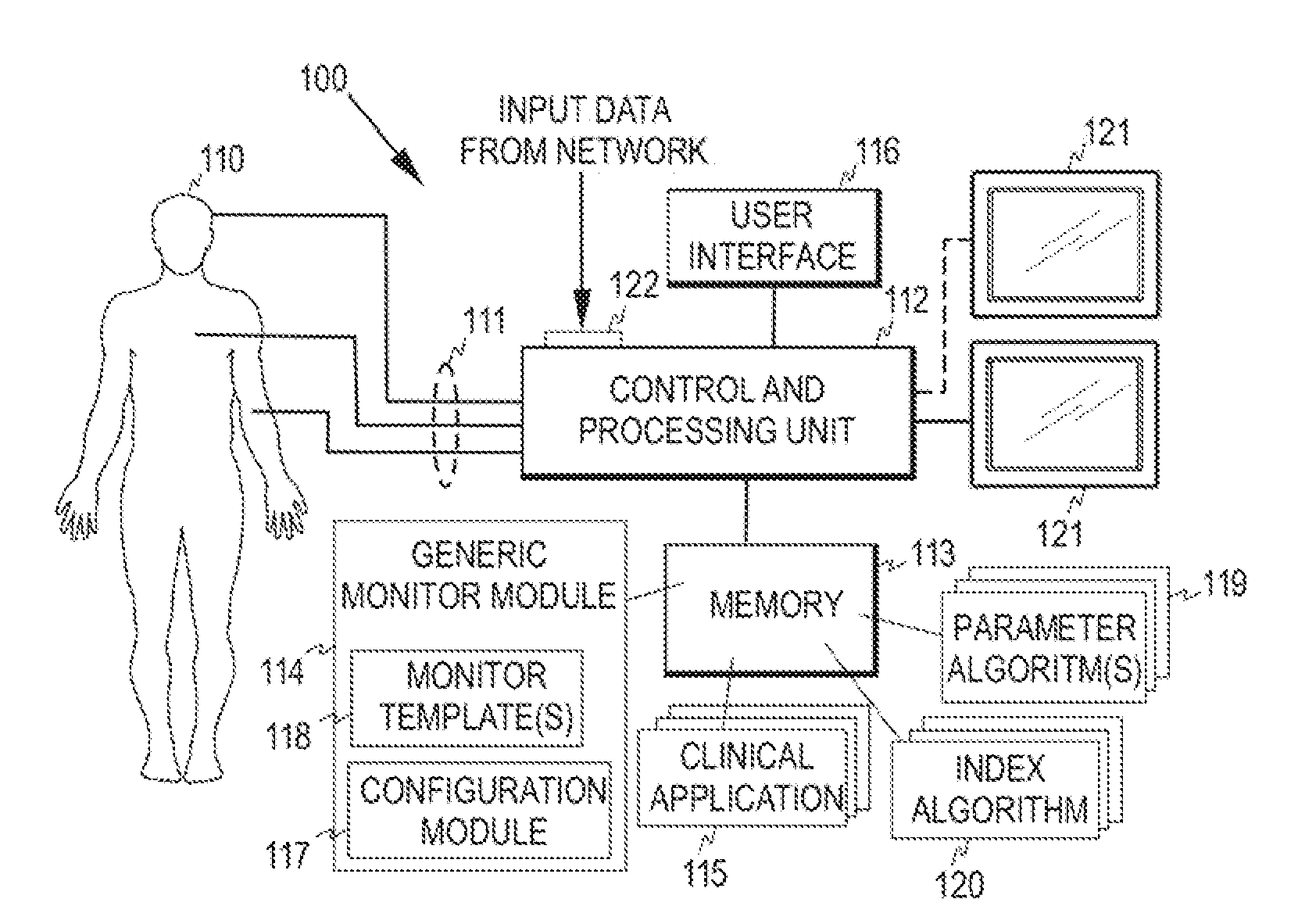
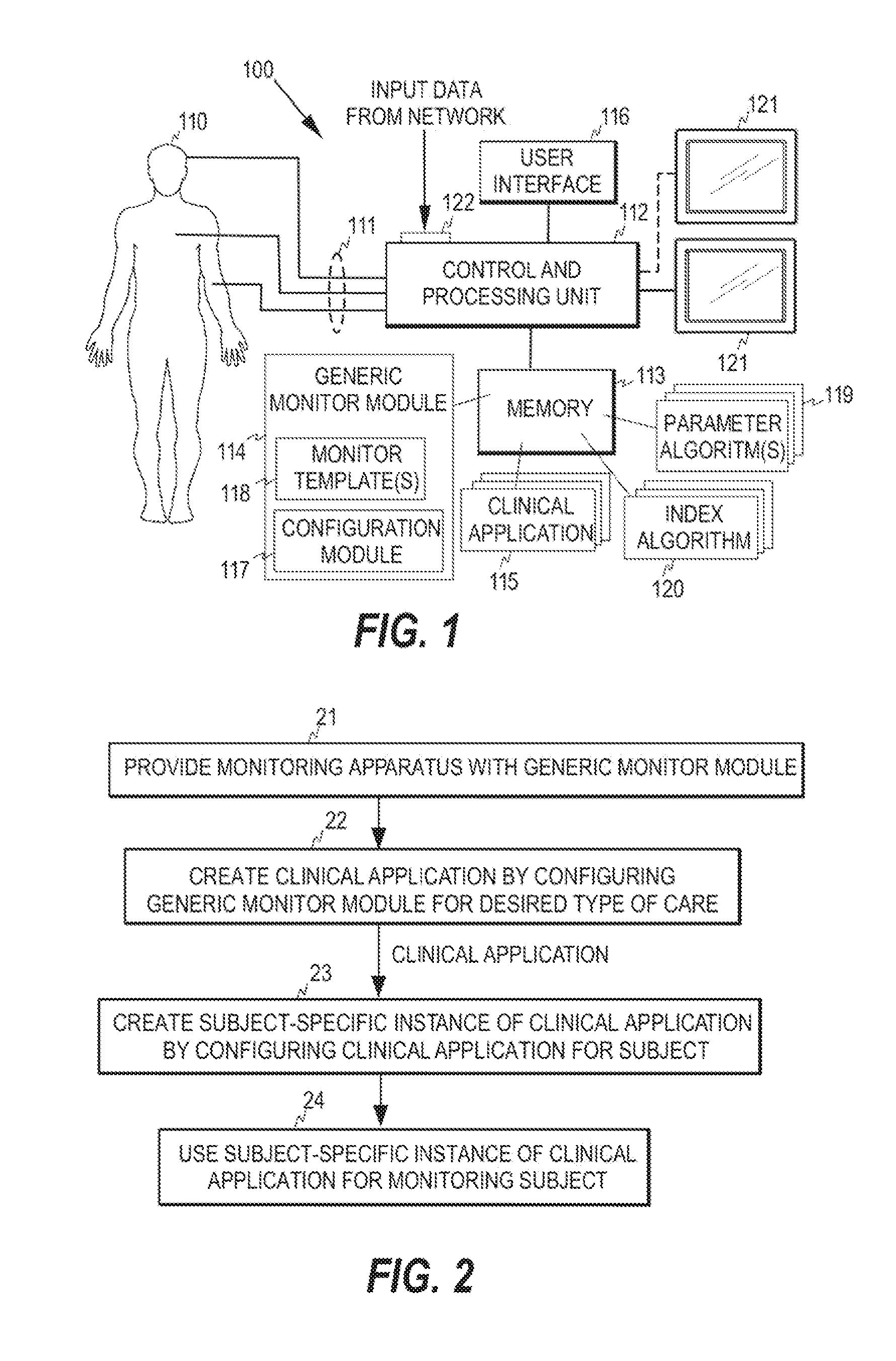
[0017]FIG. 1 illustrates one embodiment of a monitoring apparatus / system 100 for monitoring a subject 110. A monitoring apparatus / system normally acquires a plurality of physiological signals 111 from the subject, where one physiological signal corresponds to one measurement channel. The physiological signals typically comprise several types of signals, such as ECG, EEG, blood pressure, respiration, and plethysmographic signals. Based on the raw real-time physiological signal data obtained from the subject, a plurality of physiological parameters may be determined. A physiological parameter here refers to a variable calculated from the waveform data of one or more of the physiological signals acquired from the subject. If a physiological parameter is derived from more than one physiological signal, i.e. from more than one measurement channel, the said physiological signals are usually of the same signal type. The physiological parameter may thus also represent a waveform signal valu...


PUM


Abstract

A method, device, and computer program product for monitoring a subject receiving care are disclosed. To enable creation of different clinical applications with visually informative user interfaces similar to each other, a monitoring apparatus is provided with a generic monitor module serving as a template for creation of monitoring instances. At least one clinical application may be created from the generic monitor module, wherein each clinical application defines a care process for caring a subject, and a subject-specific monitoring instance may be produced from any of the at least one clinical application, thereby to obtain a runtime monitoring instance. The runtime monitoring instance may then be employed for monitoring the subject online.

Description

BACKGROUND OF THE INVENTION[0001]This disclosure relates generally to patient monitoring. More particularly, the present invention relates to monitoring a subject that receives care according to a certain care process planned for him / her.[0002]Patient monitors are electronic devices designed to display physiological information about a subject. Electrocardiogram (ECG), electroencephalogram (EEG), plethysmographic signals, and signals related to blood pressure, temperature, and respiration represent typical physiological information contained in full-size patient monitors. Patient monitors are typically also furnished with alarming functionality to alert the nursing staff when a vital sign or physiological parameter of a patient exceeds or drops below a preset limit. Alarms are normally both audible and visual effects aiming to alert the staff to a life-threatening condition or to another event considered vital. In most monitors, the alarm limits may be defined by the user, since the...

Claims


Application Information

Patent Timeline
Patent Type & Authority Applications(United States)
IPC IPC(8): A61B5/00
CPCA61B5/02055A61B5/021A61B5/02455A61B5/0402G06F19/3487A61B5/08A61B5/14551A61B5/7275G06F19/345A61B5/0476A61B5/318A61B5/369G16H15/00G16H50/20
Inventor RANTALA, BORJE
Owner GENERAL ELECTRIC CO
Learn More