
Smart plug with internal condition-based demand response capability

a condition-based demand and smart plug technology, applied in the direction of emergency protective circuit arrangement, wireless architecture usage, coupling device connection, etc., can solve the problem of substantial difference in energy cost for homeowners, and achieve the effect of reducing operating costs

Active Publication Date: 2012-03-01
HAIER US APPLIANCE SOLUTIONS INC
View PDF5 Cites 68 Cited by
  • Summary
  • Abstract
  • Description
  • Claims
  • Application Information

AI Technical Summary

Benefits of technology

The patent describes a load switch or smart plug that can monitor physical variables, such as room temperature, and control the on and off condition of a plug based on those measurements. The switch can receive input data from a remote measuring transducer and compare it to pre-set conditions to selectively control the plug. The switch can also communicate with a central controller to receive utility pricing data or peak demand events and adjust the set points accordingly. The method allows non-smart devices to shed load and reduce operating costs in response to demand response signals. The patent also mentions that the technology can be used in areas where manufacturers have not adapted their products to the new smart technology. The main technical effect of the patent is to provide a cost-effective solution for controlling plug-in devices in response to demand signals.

Problems solved by technology

Consequently, operating a particular home device during the different rate periods can result in a substantial difference in energy cost to the homeowner.

Method used


Image

  • Smart plug with internal condition-based demand response capability
  • Smart plug with internal condition-based demand response capability
  • Smart plug with internal condition-based demand response capability

Examples


Embodiment Construction

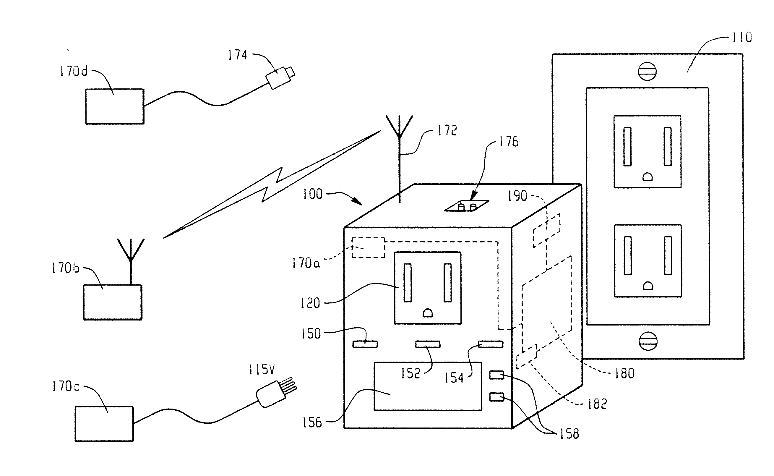
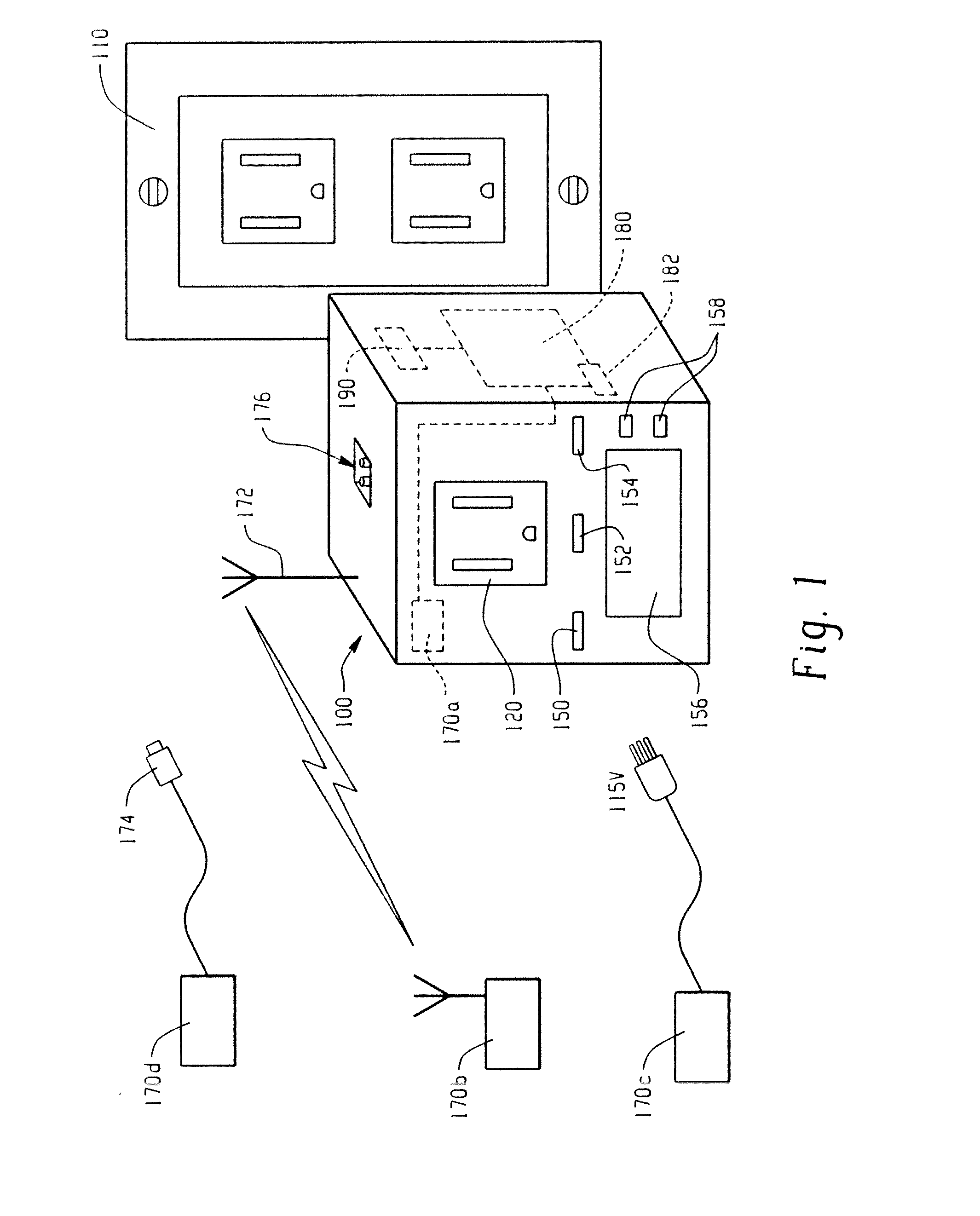
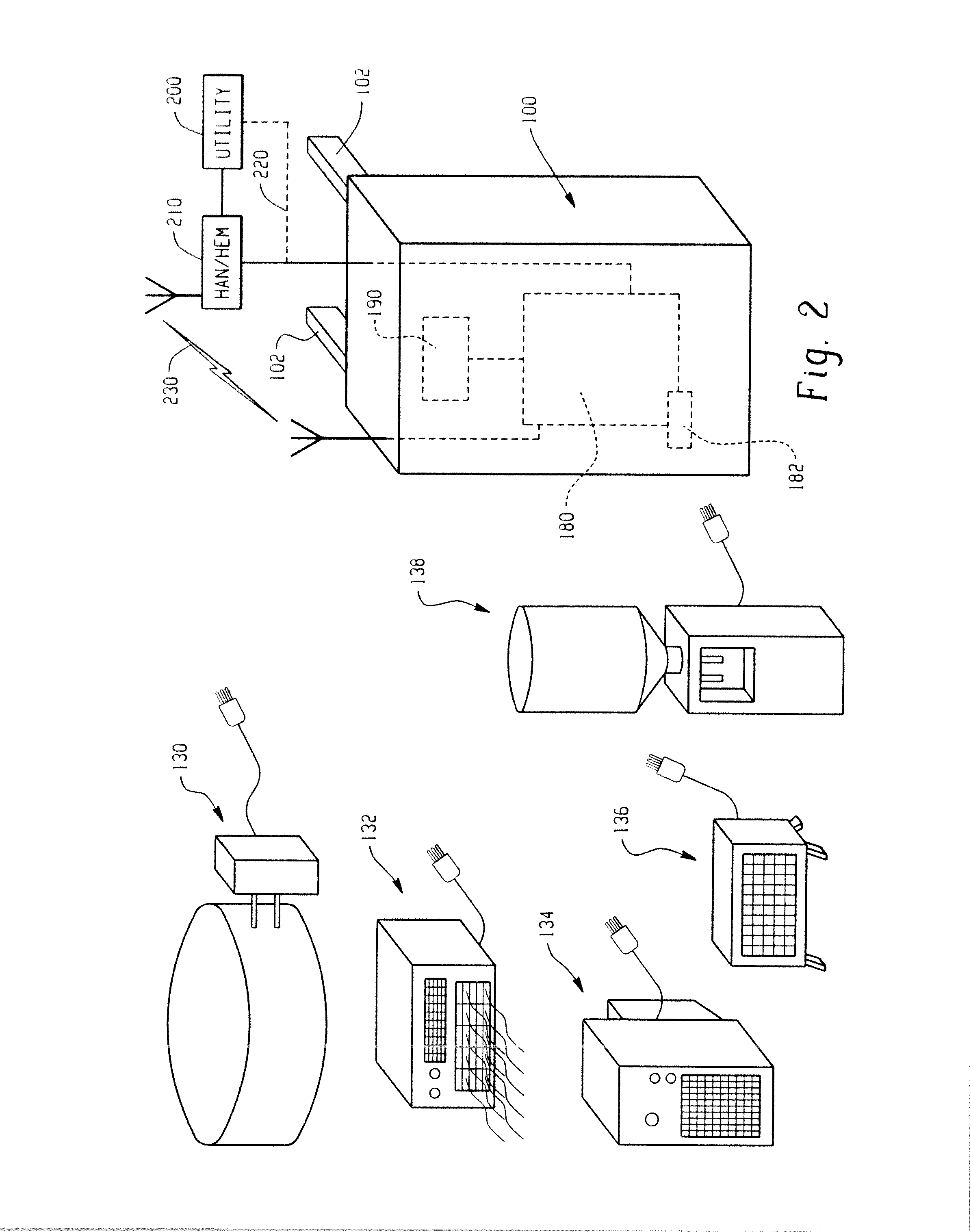
[0024]Turning to the FIGURES, there is shown a smart load switch or smart plug 100 that includes electrical contacts 102 (FIG. 2) for receipt in a grounded receptacle 110 (FIG. 1). In addition, the smart load switch 100 includes a receptacle 120 shown here as being on the surface opposite that of the electrical contacts 102 (although that need not necessarily be the case) for receipt of plug contacts associated with a remote plug-in device such as a pool heater 130, a window air conditioner 132, a dehumidifier 134, a space heater 136, or a water chiller 138. Each of these remote plug-in devices has an electrical cord that is adapted for receipt in an electrical receptacle 110, and as a result of the present disclosure, is instead received in the receptacle portion 120 of the smart load switch which, in turn, is received in or plugged in to the electrical receptacle 110. The various remote plug-in devices shown in FIG. 2 are exemplary only and, as one skilled in the art will understa...


PUM


Abstract

A smart load switch or smart plug incorporates a built-in circuit that can monitor a physical variable condition and compare that sensed condition to data stored in a memory. A controller receives input data from the measuring device, compares the data to the reference data in memory, and selectively controls the on / off condition of a switch and thus the device that is plugged into the switch.

Description

BACKGROUND OF THE DISCLOSURE[0001]The present disclosure generally relates to energy management, and more particularly to energy management or demand supply management (DSM) of household consumer devices. The disclosure finds particular application in modifying or incorporating energy savings features and functions via a smart load switch that includes a built-in circuit that responds to incoming demand response signals from utilities to shed load and reduce operating costs for the homeowner. The concept will also find application with regard to various home devices such as window air conditioners, pool heaters, dehumidifiers, space heaters, water chillers, etc.[0002]A number of companies are currently offering smart devices that are linked to a smart meter or to a home energy management (HEM) system which, in turn, is linked to the smart meter or linked to some other communication system. This allows the device to obtain data or inputs coming into a home area network from outside t...

Claims


Application Information

Patent Timeline
Patent Type & Authority Applications(United States)
IPC IPC(8): H02J3/14
CPCG01K3/005H01R31/065H02J3/14G01K13/00H04Q2209/30Y02B90/226Y04S20/16H04Q2209/43H04Q2209/60H04Q9/00H02J2310/64Y04S50/10Y02B90/20Y04S20/00
Inventor BESORE, JOHN K.BCYCRLE, MICHAEL THOMAS
Owner HAIER US APPLIANCE SOLUTIONS INC
Learn More