
Optical reader using distance map decoding

a distance map and optical reader technology, applied in the field of optical scanning systems, can solve the problems of adding cost, complicated improvements, and limited working range of conventional optical scanning systems, and achieve the effects of reducing the cost of operation, and increasing the cost of operation

Active Publication Date: 2012-03-01
HAND HELD PRODS
View PDF4 Cites 9 Cited by
  • Summary
  • Abstract
  • Description
  • Claims
  • Application Information

AI Technical Summary

Problems solved by technology

Conventional optical scanning systems, such as hand-held barcode laser scanners, typically have a limited working range due to the constraints imposed on the optical assembly.
Motorized systems with additional lenses or mirrors have been developed to re-position the laser beam waist relative to the fixed lens assembly, thereby increasing the working range of the scanning apparatus, but such improvements are complicated and add cost.
Decoding images has always proved challenging, in part because decoding systems work best with a sharp representation of the barcode symbol, and a sharp representation is not always possible.
Due to optical, environmental or physical factors, the representation may be out of focus, too close to the reader, or too far away from the reader.
This solution can be cumbersome, frustrating, or may not even be possible.
Analog circuits using this approach are bulky and consume power, which has a deleterious effect on battery life.
Digital circuits using this approach rely on advances in microprocessing speed, but are still slow due to the enormous number of iterations required to properly identify and verify a valid codeword.

Method used


Image

  • Optical reader using distance map decoding
  • Optical reader using distance map decoding
  • Optical reader using distance map decoding

Examples


Embodiment Construction

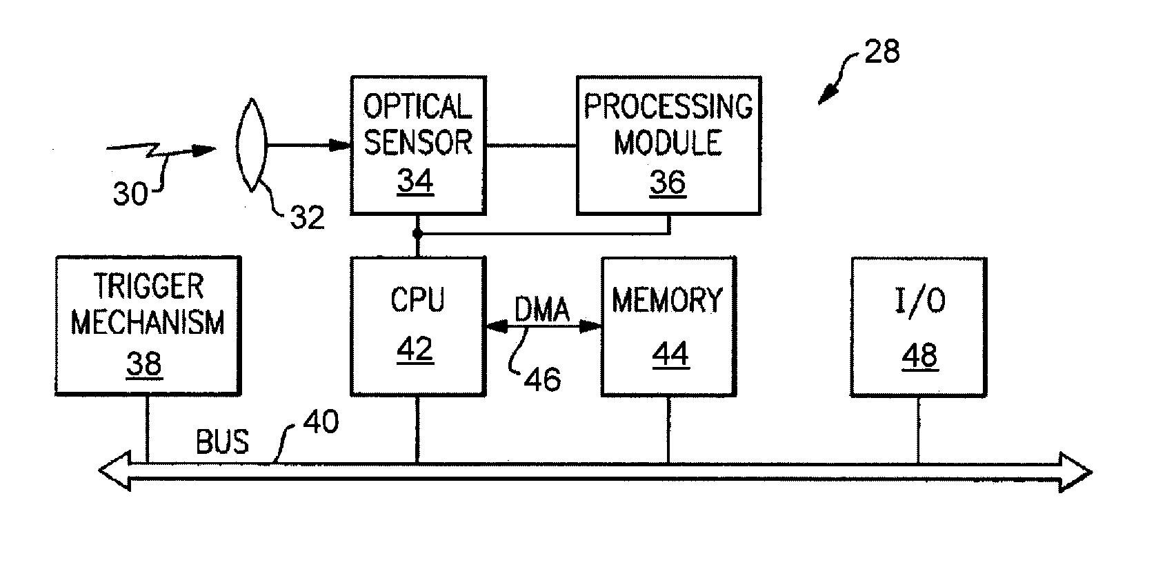
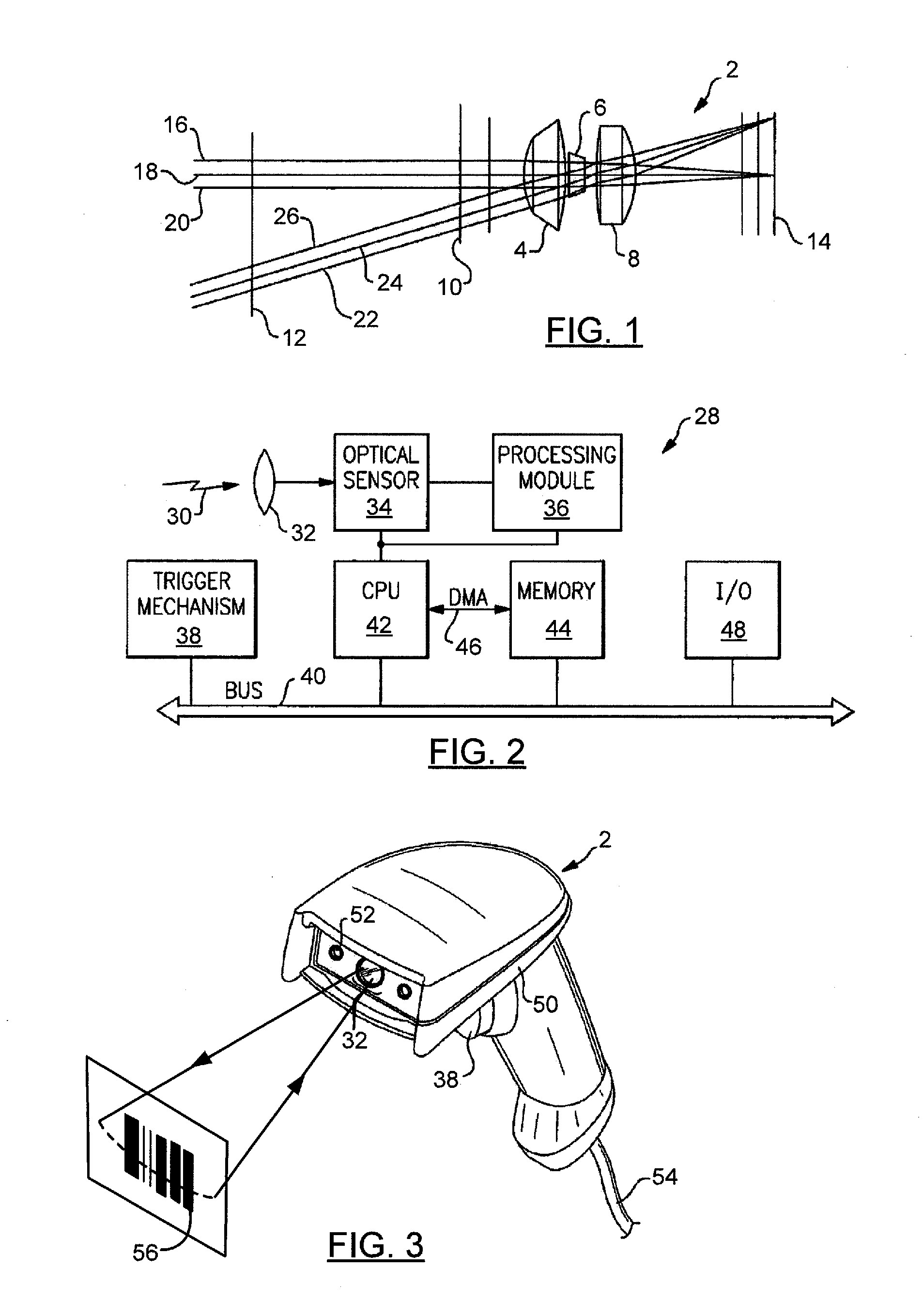
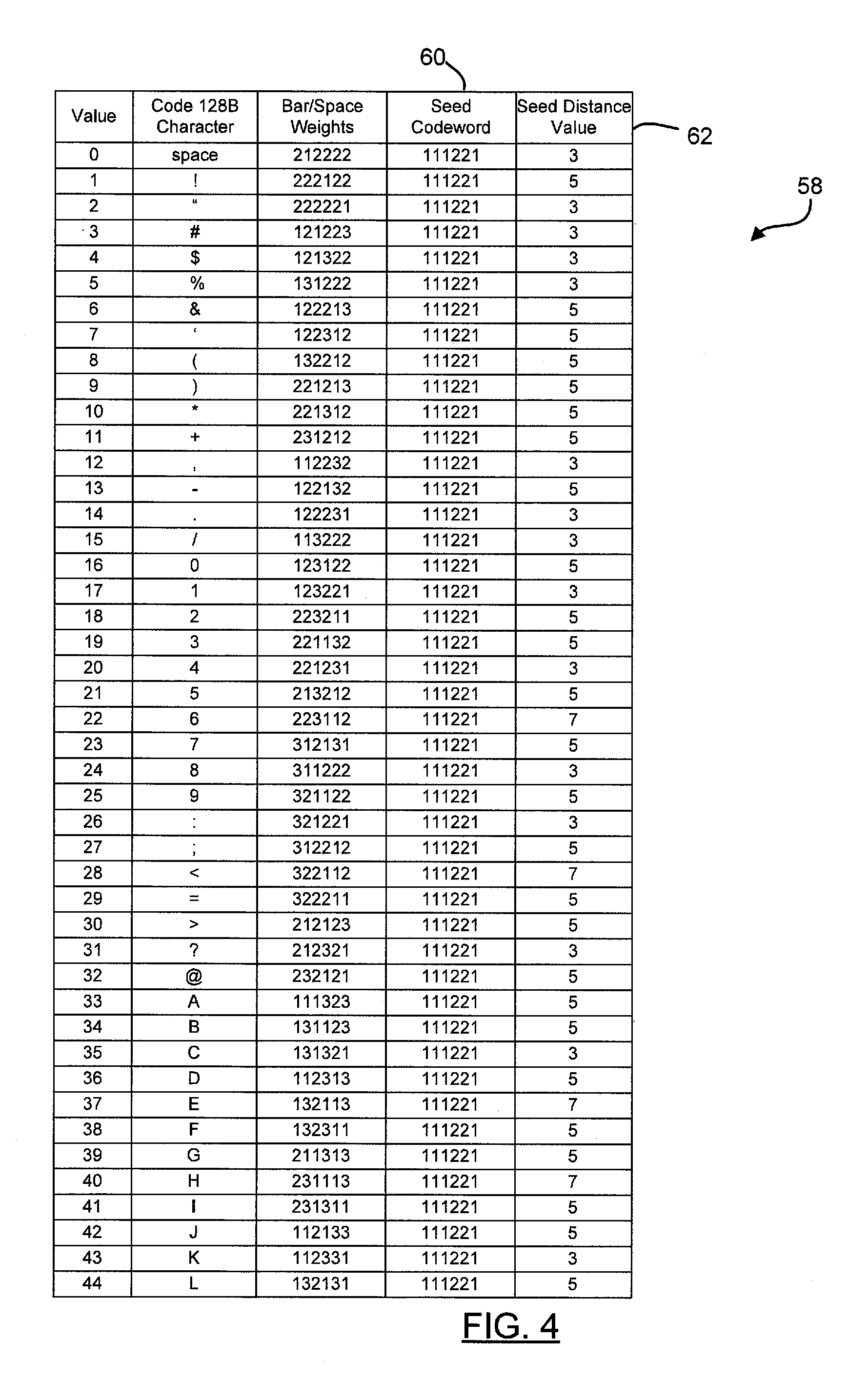
[0017]In a barcode image, some a priori knowledge is available of what the particular barcode is expected to look like, and hence how it is expected to appear in coded form. For example, a barcode image may comprise one or more bars and spaces (i.e., is represented by a step function, or in some embodiments, is a function representable as a gray scale). When imaged with an imaging engine or a barcode reader, the barcode is represented as a codeword, or character, having a sequence of binary, or in some cases, gray scale, values. In principle, a decode table which defines the exact step function (or gray scale value) of each valid character is available. However, checking each barcode image against every entry in a decode table is time-consuming, even for modern processors. The systems and methods of the present invention provide a means by which the barcode image may be accurately decoded by checking only a small subset of the decode table, thereby decreasing the decode time.

[0018]A...


PUM


Abstract

A method for decoding an encoded candidate character of a symbology is provided that includes the steps of providing a plurality of valid barcode characters of a symbology having n elements, generating a seed codeword comprising n elements, computing a seed distance value from the seed codeword to each character in the symbology, generating a distance map comprising each character in the symbology and the associated computed seed distance value, and arranging the plurality of seed distance values into a plurality of bins. Each bin contains a subset of the characters in the symbology. The method includes the steps of selecting a candidate barcode character for decoding, computing a candidate distance value from the candidate barcode character to the seed codeword, identifying the bin containing the candidate distance value, and comparing the candidate barcode character with the valid barcode characters in the bin having the candidate distance value.

Description

FIELD OF THE INVENTION[0001]This invention relates generally to the field of optical scanning systems, and more particularly to a system and method for decoding images that increases performance of the system.BACKGROUND OF THE INVENTION[0002]Various optical scanning apparatus have been developed to read and decode optical indicia, such bar as code symbols on a target such as a label. While early barcode scanners were designed to read symbols at a relatively close distance, there exists a need to read symbols at greater and greater distances, for example in warehousing environments. Conventional optical scanning systems, such as hand-held barcode laser scanners, typically have a limited working range due to the constraints imposed on the optical assembly. Motorized systems with additional lenses or mirrors have been developed to re-position the laser beam waist relative to the fixed lens assembly, thereby increasing the working range of the scanning apparatus, but such improvements a...

Claims


Application Information

Patent Timeline
IPC IPC(8): G06K7/14
CPCG06K7/1404
Inventor WANG, YNJIUN P.
Owner HAND HELD PRODS
Learn More