
Solar Array Recombiner Box With Wireless Monitoring Capability

a solar array and wireless monitoring technology, applied in the field of solar array recombiner boxes, can solve the problems of inability to meet the needs of non-renewable resources, inability to scale up the production of solar energy, and inability to meet the needs of renewable resources

Active Publication Date: 2012-03-01
SHOALS TECH GROUP
View PDF18 Cites 20 Cited by
  • Summary
  • Abstract
  • Description
  • Claims
  • Application Information

AI Technical Summary

Benefits of technology

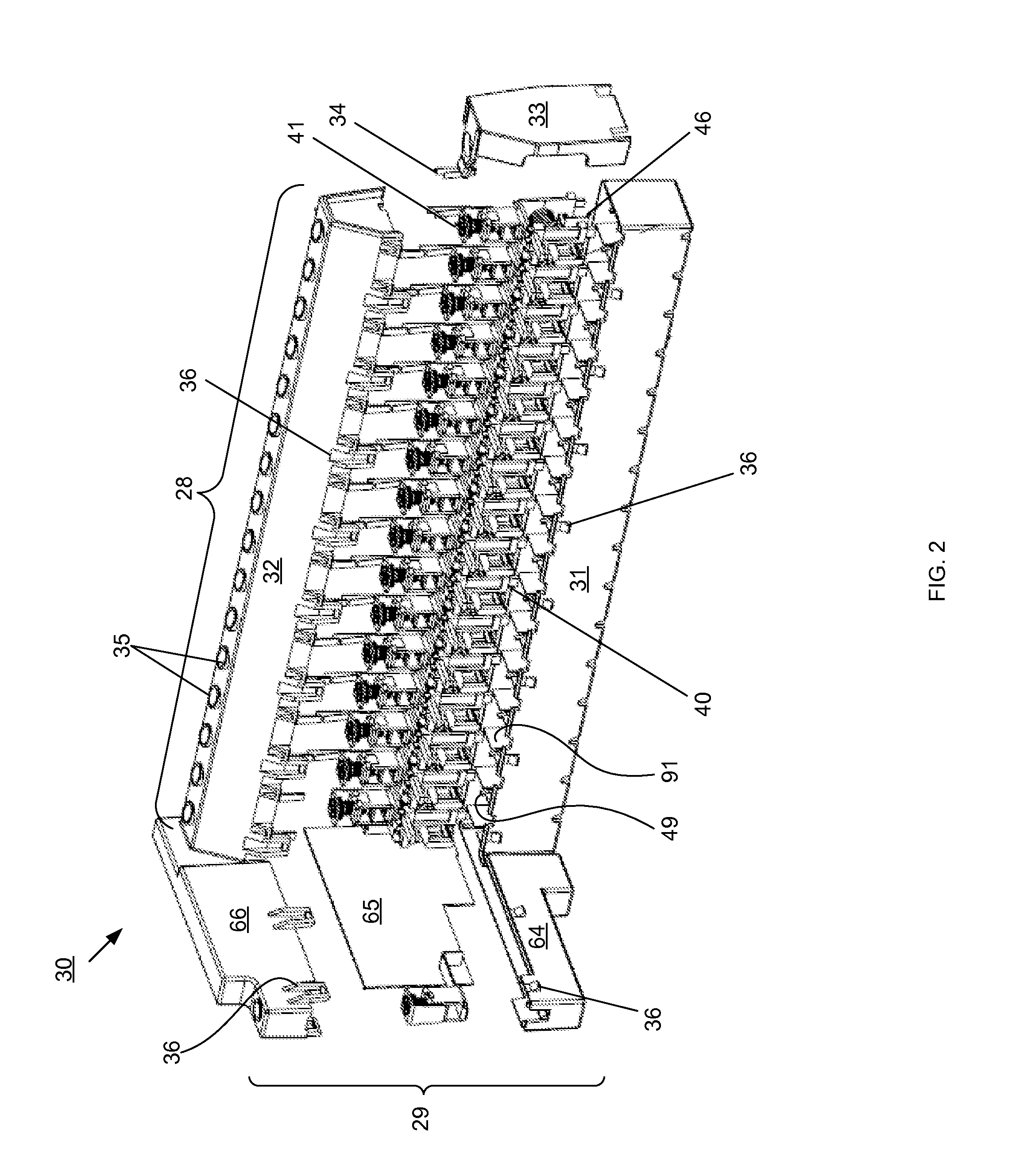
[0010]The sensor control module “plugs” into fuses in a recombiner box, with each fuse in the recombiner box corresponding with one string of solar panels in a solar array. In this manner the sensor control module monitors the system for, for example, degradation in current, which could indicate a solar panel in an array is not operating properly. The sensor control module is L-shaped, and can be fitted into commercially available recombiner boxes. Alternatively, recombiner boxes can be built including the monitoring system. The sensor control module includes a plurality of magnetized cores and Hall effect sensors for measuring the current for each array of solar panels. The sensor control module also includes a connection to a bus bar, for measuring the voltage of the entire array. The brain assimilates this data and sends it to the RF controller for dissemination to other receivers in the mesh network, or to the central processor.

Problems solved by technology

As the world's energy demands have increased, it has become clear that dependence on non-renewable resources is not sustainable from a supply or environmental standpoint.
However, the large-scale production of solar energy requires infrastructure beyond a sunny field full of solar collectors.
Solar collectors, by design, are typically somewhat fragile.
Given the propensity to break, and the exposure to outdoor variations and hazards, solar collectors experience fluctuations in energy output, technical difficulties, and / or outright failure.
Others have attempted to monitor the output of solar arrays, but known systems are wired, complicated, cumbersome, not amenable to retrofitting pre-existing combiner boxes, and / or difficult to integrate with an existing system.

Method used


Image

  • Solar Array Recombiner Box With Wireless Monitoring Capability
  • Solar Array Recombiner Box With Wireless Monitoring Capability
  • Solar Array Recombiner Box With Wireless Monitoring Capability

Examples


Embodiment Construction

[0031]In the following description, like reference characters designate like or corresponding parts throughout the several views. It should be understood that the following descriptions and illustrations describe preferred embodiments of the inventions, but are not intended to limit the inventions thereto.

[0032]As used herein, “recombiner box” and “combiner box” are interchangeable terms, and the inventions can be used with either configuration.

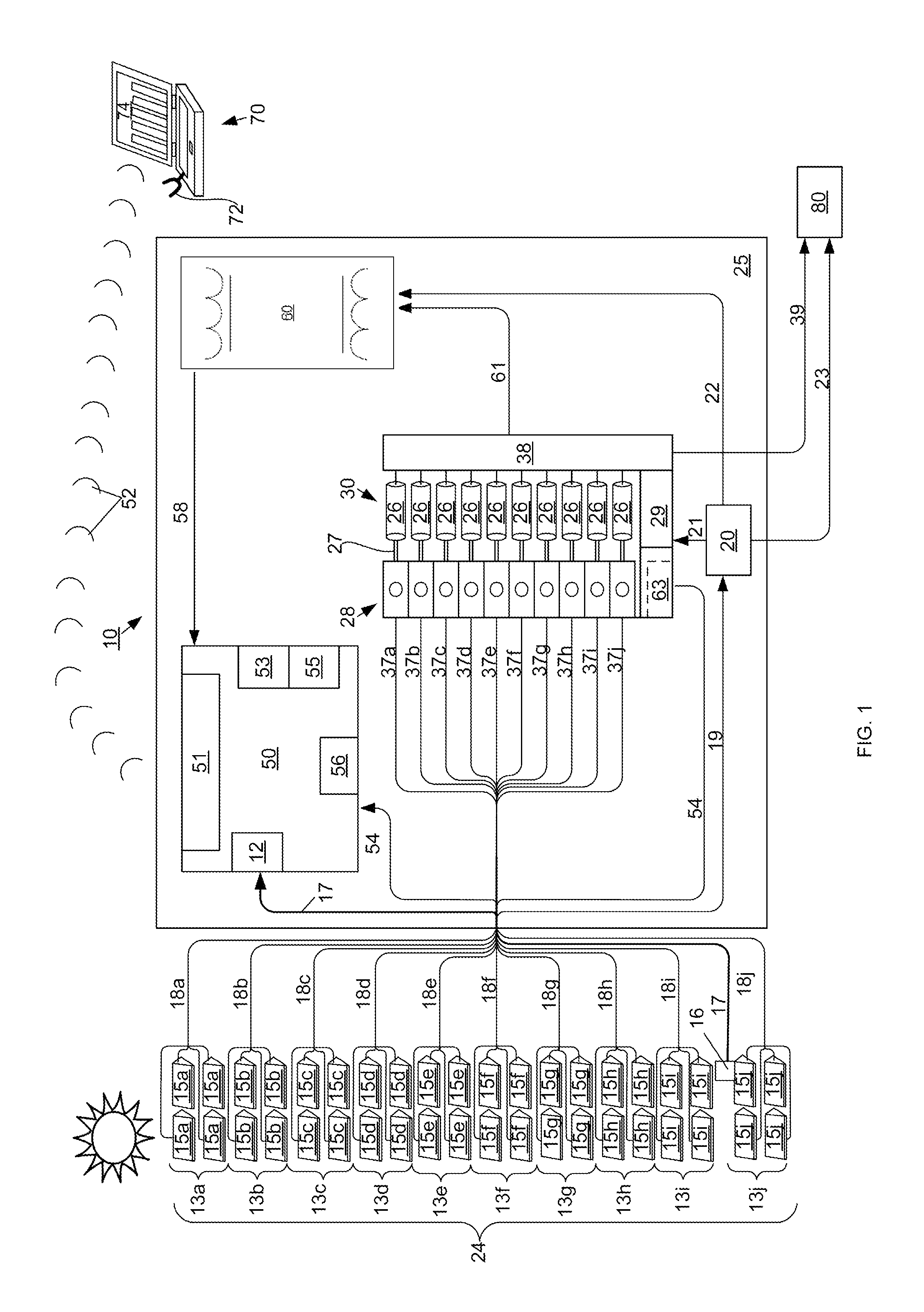
[0033]FIG. 1 provides an overview of monitoring system 10 and some associated interconnections. Solar panels 15, individually designated as 15a, 15b, 15c and so on, collectively form corresponding solar arrays 13a, 13b, 13c and so on. Solar panels 15 are wired to system 10 by monitoring input branch 18, with individual wires designated as 18a, 18b 18c and so on, corresponding to individual solar arrays 13a, 13b, 13c and so on. Temperature sensor 16 preferably measures ambient, but can also measure the temperature of specific components of pan...


PUM


Abstract

A system for monitoring and wirelessly transmitting solar array parameters such as current, voltage and temperature in real time is primarily housed within a recombiner box. The system lends itself to retrofitting within some commercially available recombiner boxes. Signals emitted from the RF controller component of the system are received by a central processor, which includes a dashboard interface. Multiple systems in proximity can be linked to form a mesh network with one central processor.

Description

BACKGROUND[0001](1) Field[0002]The present invention relates generally to recombiner boxes used in the solar industry and, more particularly, to recombiner boxes capable of monitoring the energy output of solar panels in an array, and wirelessly transmitting output data to a central processor.[0003](2) Related Art[0004]As the world's energy demands have increased, it has become clear that dependence on non-renewable resources is not sustainable from a supply or environmental standpoint. Thus, more attention is being paid to so-called alternative energy such as wind and solar. This attention has led to significant advances in alternative energy technology, to the point that utility companies are increasingly interested in solar generated energy. However, the large-scale production of solar energy requires infrastructure beyond a sunny field full of solar collectors.[0005]Solar collectors, by design, are typically somewhat fragile. In addition, for high-output production, for example ...

Claims


Application Information

Patent Timeline
Patent Type & Authority Applications(United States)
IPC IPC(8): H01L31/042
CPCG01D4/002H01L31/02021H01L31/042Y02E10/50Y02B70/346Y02B90/241H01L2924/0002Y04S20/32Y04S20/525H02S50/10H01L2924/00G01D2204/35Y02B70/34Y02B90/20Y04S20/30
Inventor SOLON, DEAN
Owner SHOALS TECH GROUP
Learn More