Communication Method In An Automatic System

Inactive Publication Date: 2012-02-23
SIEMENS AG
View PDF0 Cites 2 Cited by
  • Summary
  • Abstract
  • Description
  • Claims
  • Application Information

AI Technical Summary

Benefits of technology

[0014]It is an object of the present invention to provide a communication method in an automation system, in which determinate and real-time communication can be performed in a practical way in the automation system by using the method, so as to have the communication cycle time shortened as much as possible.
[0022]The present invention provides a method with stronger certainty for the communication between the access point and the client terminals. First of all, the present method can not only strictly control the downlink data transmission through the access point but also strictly control the uplink data transmission via the access point. Secondly, the method of the present invention expands the original MRA solution, dividing a master-MRA phase and a slave-MRA phase for data retransmission based on the MRA, which makes the present invention have more practical applicability. Furthermore, the present invention further divides the MMP frame into a master-MMP frame and a slave-MMP frame. As compared to the MMP, the slave-MMP frame replaces the function of performing acknowledgement of the uplink in the MMP, and as compared to the MRA solution, the cycle time is further shortened.

Problems solved by technology

Therefore, the difficulties faced by such cyclic communication systems, with the PNIO communication as an example, are: first of all, the initial communication certainty between the I / O controller and the I / O devices needs to be ensured, i.e., the I / O controller is made to communicate with a designated I / O device within a determined time period.
Secondly, the cycle time should number of the I / O devices is increased.
However, in WLAN communication based on the PNIO protocol, the difficulties faced by the cyclic communication are even more prominent.
It is apparent that since the data volume to be transmitted by some client terminals may be very large, it is very difficult for this solution to ensure the certainty and instantaneity of the communication.
However, in these two solutions, in order to ensure that each device is able to transmit data, a large amount of additional overheads are required, and these overheads would then increase the cycle time.
Although the PCF solution has a degree of certainty in communication, it does not have complete certainty.
It is still not possible, however, to ensure communication certainty over the uplink.
For example, the packet sent by STA1 to the access point AP may be very long, so that the access point AP cannot be certain about the specific time when the packet to STA2 is sent the next time.
In addition, at the moment, the PCF solution still does not have effective hardware support.
However, there are still problems when the MRA solution is used in communication.
Firstly, the acknowledgement BA for the uplink packet takes a relatively long time.
However, the acknowledgement for the uplink packet cannot be achieved in the way mentioned above.
In this way, in the case where there are quite a few client terminals, the access point will take a relatively long time to perform acknowledgement of the uplink data sent by each client terminal.
Secondly, the MRA solution only provides a basic data transmission sequence but does not give consideration to a retransmission mechanism when errors occur in the packets.
Therefore, the application of the MRA solution is limited.

Method used


Image

  • Communication Method In An Automatic System
  • Communication Method In An Automatic System
  • Communication Method In An Automatic System

Examples


Embodiment Construction

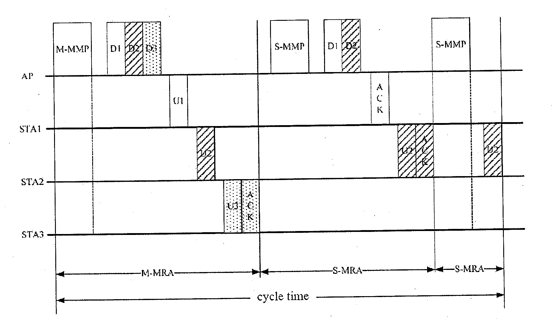
[0033]FIG. 5 is a schematic diagram of a sequence that uses the master-slave MRA method of the present invention to perform data exchange. The automation communication system in FIG. 5 comprises an access point AP and three client terminals STA1, STA2, and STA3. The access point AP sends downlink data to the client terminals STA1, STA2, and STA3, and the client terminals STA1, STA2, and STA3 respectively send uplink data to the access point AP.

[0034]In accordance with the method of the present invention, the data exchange process between the access point AP and three client terminals STA1, STA2, and STA3 is divided into two phases, which respectively are a master multiple receiver aggregation phase (Master-MRA) and two slave multiple receiver aggregation phases (Slave-MRAs).

[0035]During the master multiple receiver aggregation phase (Master-MRA), the access point AP aggregates the data to be sent to client terminals STA1, STA2, and STA3 into one packet, which packet includes a maste...


PUM


Abstract

A communication method in an automation system, wherein the system comprises an access point and client terminals that receive downlink data sent from the access point and send uplink data to the access point, and the data transmission is divided into a master multiple receiver aggregation phase and more than one slave multiple receiver aggregation phases. During the master multiple receiver aggregation phase, the access point aggregates the data to be sent to the plurality of client terminals into one packet for transmitting in the downlink, and during the slave multiple receiver aggregation phases, the access point aggregates data in which errors have occurred when being transmitted during the master multiple receiver aggregation phase into one packet for transmitting in the downlink. The method can have strict control, through the access point and over the uplink and downlink data transmission, thus enhancing the certainty during automation communication and further reducing the cycle time.

Description

CROSS-REFERENCE TO RELATED APPLICATIONS[0001]This is a U.S. national stage of application No. PCT / CN2009 / 071582 filed 30 Apr. 2009, the content of which is incorporated herein by reference in its entirety.BACKGROUND OF THE INVENTION[0002]1. Field of the Invention[0003]The present invention relates to a communication method in an automation system and, more particularly, to a communication method which is used to perform real-time deterministic communication in an automation system.[0004]2. Description of the Related Art[0005]In the series of automation products SIMATIC, the PROFINET IO protocol (PNIO protocol) is used between distributed I / O devices and an I / O controller to perform fast and effective data exchange. The PROFINET IO protocol introduces the industrial Ethernet technology into the field at first level. The PNIO communication is acyclic communication, and in this communication mechanism, the I / O controller communicates with each of the I / O devices one by one within a tim...

Claims


Application Information

Patent Timeline
IPC IPC(8): H04W4/06
CPCH04L1/1607H04W28/06H04W28/04
Inventor LAMPE, MATTIASLI, HUIMULLER, JORGTIAN, JI FENG
Owner SIEMENS AG
Why Eureka
Try Eureka