Aperture adjusting device

Active Publication Date: 2012-02-23
DELTA ELECTRONICS JIANGSU +1
View PDF2 Cites 0 Cited by
  • Summary
  • Abstract
  • Description
  • Claims
  • Application Information

AI Technical Summary

Benefits of technology

[0016]An objective of the present invention is to provide an aperture adjusting device, which is provided with a long guiding slot to enlarge a swingable range of a blade to improve the covering ratio of the aperture.
[0018]Thereby, the support frame of this embodiment the present invention can provide a large area for extending the first guiding slot, so that both the rotary range of the gear ring and the swingable range of the blade are enlarged to result in an increased covering ratio of the aperture. Additionally, the need of disposing a guiding slot in the gear ring is eliminated, so that both the size and the weight of the gear ring can be reduced to reduce the torsional force required to drive the gear ring.

Problems solved by technology

However, there is a limitation on the extent to which the number of teeth of the driving gear 941 can be reduced to increase the rotational speed ratio, so it is difficult to improve the rotational speed ratio of the driving gear 941 to the gear ring 92.
However, the hanging shafts 922 are difficult to manufacture and require a high manufacturing precision for the gear ring 92 to rotate smoothly.
This is unfavorable for mass production.

Method used


Image

  • Aperture adjusting device
  • Aperture adjusting device
  • Aperture adjusting device

Examples


Embodiment Construction

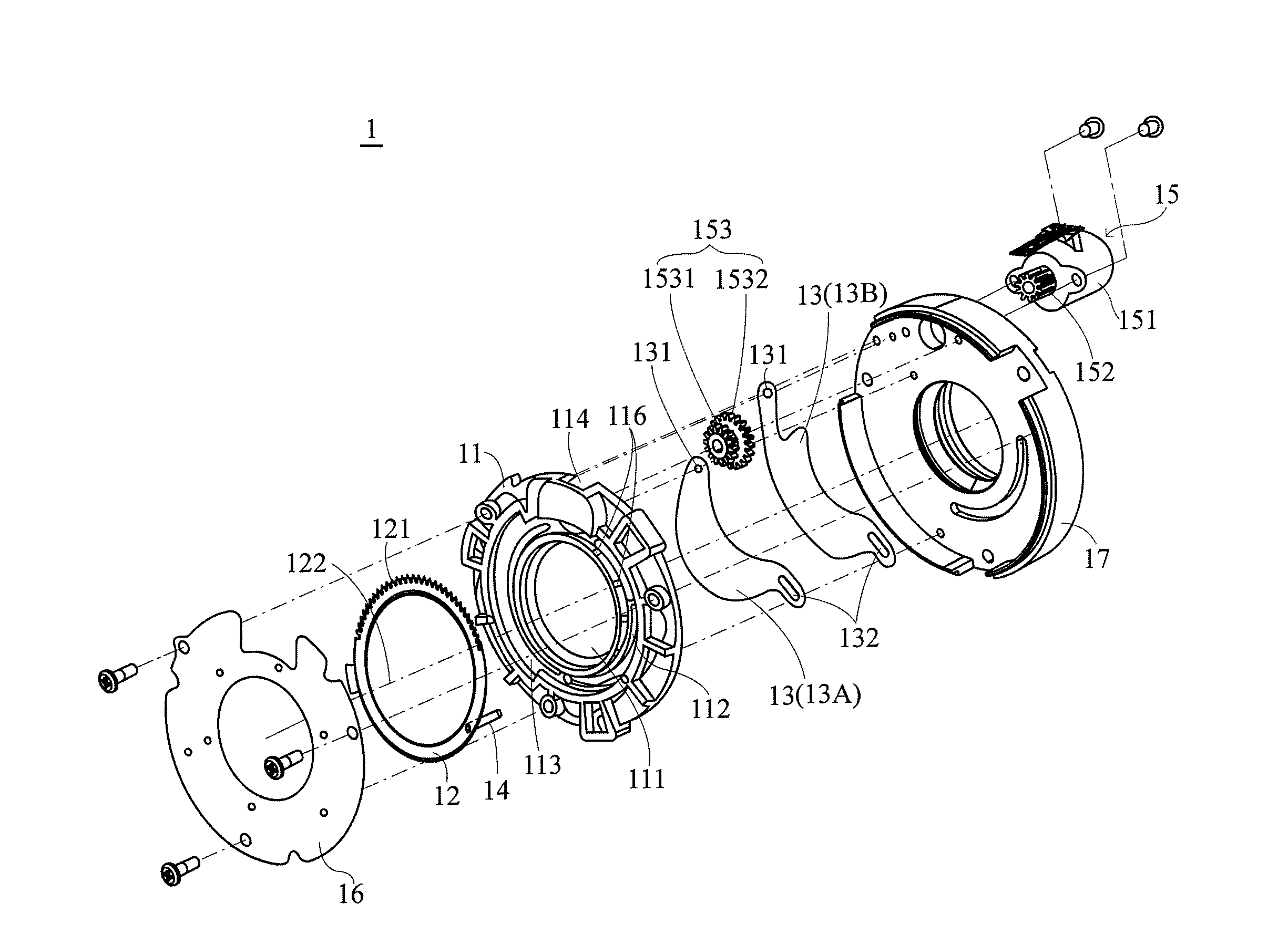
[0028]Referring to FIG. 3 through FIG. 5, a preferred embodiment of the aperture adjusting device 1 of the present invention is shown therein. The aperture adjusting device 1 may be installed in a projector (not shown) to adjust brightness of light projected by the projector. The aperture adjusting device 1 comprises a support frame 11, a gear ring 12, at least one blade 13, a connector 14 and a driving module 15.

[0029]Referring to an embodiment shown in FIG. 5 and FIG. 6, the support frame 11 may be a disc-shaped structure and have a first side and a second side opposite to the first side. Additionally, the support frame 11 comprises an aperture 111, a first guiding slot 112, a ring-shaped recess 113, a receiving space 114, a rib 115 and a plurality of protrusions 116.

[0030]The aperture 111 may be located at the center of the support frame 11, and the first guiding slot 112 is located at the periphery of the aperture 111 and extends along the circumference of the aperture 111. Both...


PUM


Abstract

An aperture adjusting device is disclosed. The aperture adjusting device includes a support frame, a gear ring, at least one blade, and a connector. The support frame includes an aperture, and a guiding slot. The gear ring is rotatably disposed on a first side of the support frame. The blade is swingably disposed on a second side of the support frame, and used to partially cover the aperture. The connector is fixed to the gear ring, and passes through the guiding slot to connect with the blade. The gear ring is adapted to rotate to make the connector move along the guiding slot to drive the blade to swing.

Description

[0001]This application claims priority to China Patent Application No. 201020507772.1 filed on Aug. 20, 2010.CROSS-REFERENCES TO RELATED APPLICATIONS[0002]Not applicable.BACKGROUND OF THE INVENTION[0003]1. Field of the Invention[0004]The present invention provides an aperture adjusting device and more particularly, to an aperture adjusting device with a gear ring.[0005]2. Descriptions of the Related Art[0006]In reference to FIGS. 1 and 2, a conventional aperture adjusting device 9 is shown therein. The aperture adjusting device 9 comprises a frame 91, a gear ring 92, a blade 93, a step motor 94 and a cover plate 95.[0007]The gear ring 92 has a guiding slot 921 and is suspended from the cover plate 95 to rotate through a plurality of shafts 922 that are slidable in a plurality of grooves 951 of the cover plate 95 respectively. The blade 93 is swingably connected to the frame 91 and partially covers the aperture 911 of the frame 91. Additionally, the blade 93 has a boss 931 extending ...

Claims


Application Information

Patent Timeline
IPC IPC(8): G02B26/02G03B9/06
CPCG03B9/02
Inventor LAI, TU FACHAN, CHIA PING
Owner DELTA ELECTRONICS JIANGSU
Why Eureka
Try Eureka