
Air-conditioning apparatus

a technology for air conditioning and equipment, applied in the field of air conditioning equipment, can solve the problems of adverse effects of refrigerant on the human body

Active Publication Date: 2012-02-23
MITSUBISHI ELECTRIC CORP
View PDF22 Cites 47 Cited by
  • Summary
  • Abstract
  • Description
  • Claims
  • Application Information

AI Technical Summary

Benefits of technology

[0012]According to the air-conditioning apparatus of the invention, since the difference between the temperatures of the secondary-side heat transfer medium at a position before and at a position after the use side heat exchanger or at a position before and at a position after the intermediate heat exchanger is controlled to be a preset target value and to be larger at the time of the heating operation than at the time of the cooling operation, the actuator can be controlled adequately in accordance with each operation mode, namely the cooling operation or the heating operation, and operation in a state of high COP can be performed.

Problems solved by technology

Also, in a normal air-conditioning apparatus, if refrigerant leaks indoors, the refrigerant can have adverse effects on the human body due to its toxicity, combustibility, and the like, whereas in the air-conditioning apparatus described above, there is no risk of any indoor leak because no refrigerant piping is provided indoors.

Method used


Image

  • Air-conditioning apparatus
  • Air-conditioning apparatus
  • Air-conditioning apparatus

Examples


embodiment 1

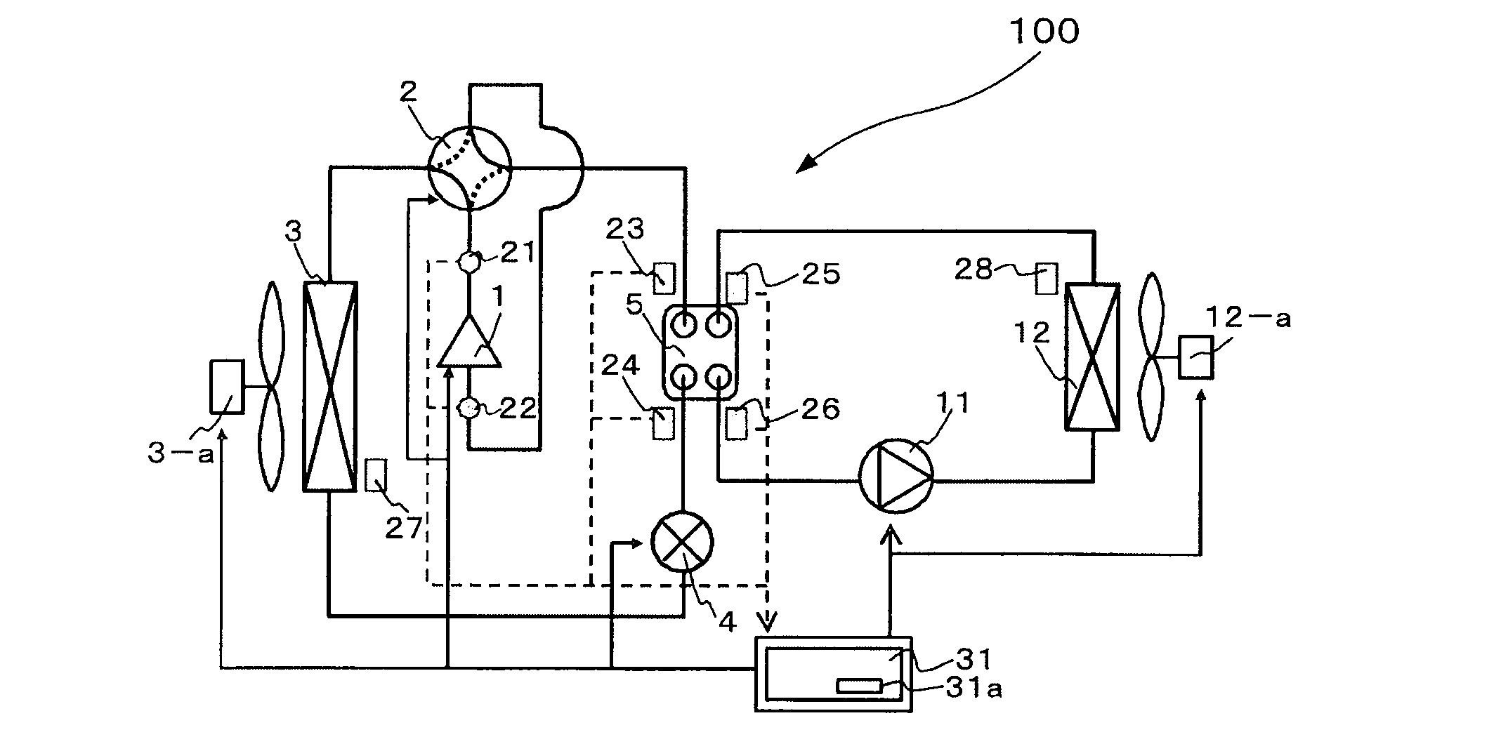
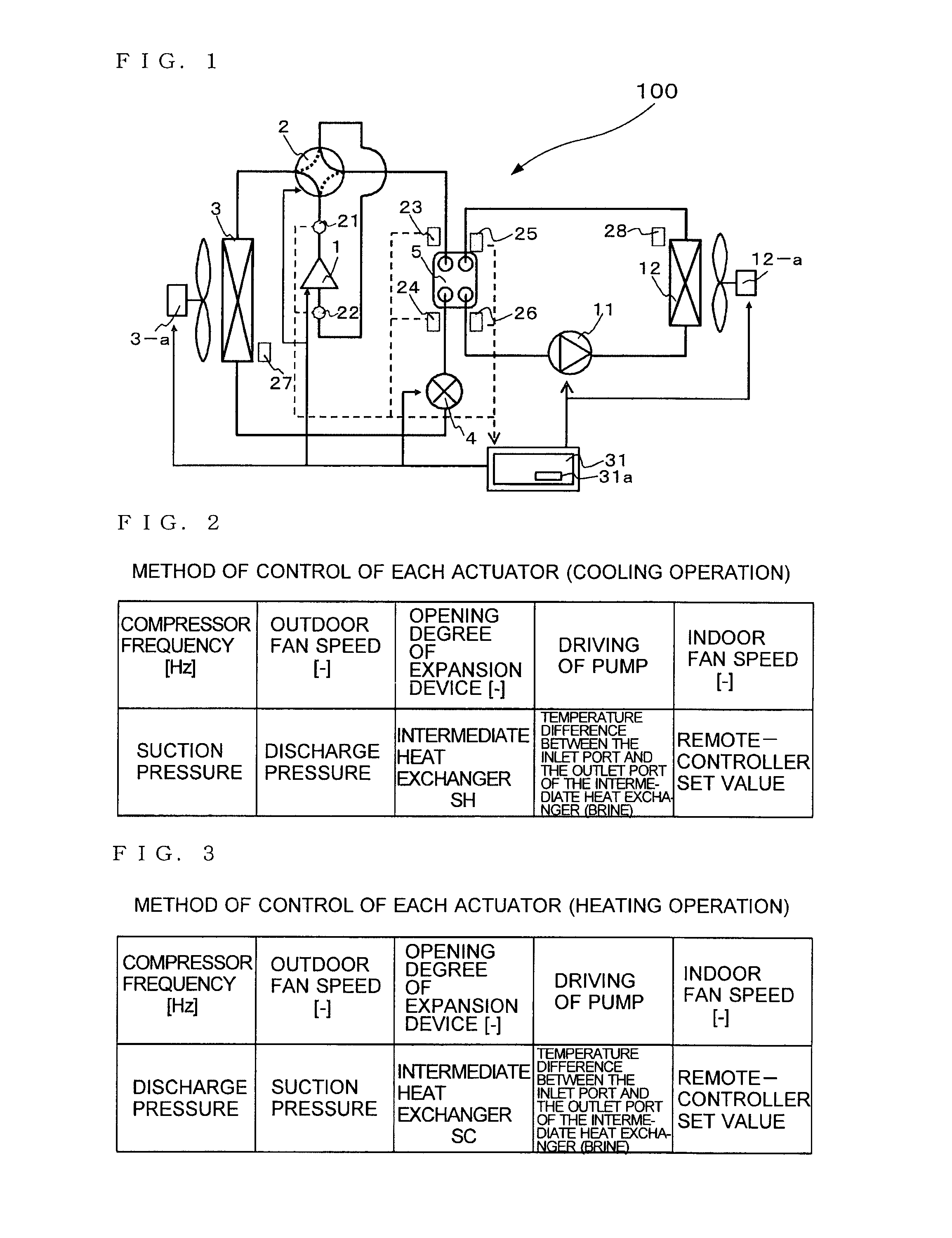
[0033]FIG. 1 is a refrigerant cycle chart showing a configuration of a refrigerant cycle in an air-conditioning apparatus 100 according to Embodiment 1 of the invention. A cycle configuration and an operation of the air-conditioning apparatus 100 will be described with reference to FIG. 1. This air-conditioning apparatus 100 is capable of cooling or heating by using refrigeration cycles (a primary-side cycle and a secondary-side cycle) in which refrigerants (a primary-side heat transfer medium and a secondary-side heat transfer medium) circulate, In the drawings shown below, including FIG. 1, the dimensional relationships of the respective components may be different from those in the actual ones.

[0034]As shown in FIG. 1, the air-conditioning apparatus 100 includes a compressor 1, a four-way valve 2, an outdoor heat exchanger (heat source side heat exchanger) 3, an outdoor fan 3-a, an expansion device 4, an intermediate heat exchanger 5, a pump 11, an indoor heat exchanger (use side...

embodiment 2

[0076]FIG. 9 to FIG. 11 are schematic drawings showing examples of installation of an air-conditioning apparatus according to Embodiment 2 of the invention. Installation of the air-conditioning apparatus according to Embodiment 2 will be described with reference to FIG. 9 to FIG. 11. This air-conditioning apparatus is a simultaneous cooling and heating air-conditioner in which a plurality of indoor devices (indoor units) are connected to one outdoor device (outdoor unit) and each indoor unit is capable of freely selecting a cooling or heating operation mode. An example in which the transport of heat from an outdoor unit A to a diversion controller B is performed using two refrigerant pipes is shown in FIG. 9 and FIG. 10, and an example in which the transport of heat from the outdoor unit A to the diversion controller B is performed using three refrigerant pipes is shown in FIG. 11.

[0077]In the air-conditioning apparatus according to Embodiment 2, the outdoor unit A is installed in a...

embodiment 3

[0084]FIG. 12 is a refrigerant cycle chart showing a configuration of a refrigerant cycle in an air-conditioning apparatus 200 according to Embodiment 3 of the invention. A cycle configuration and an operation of the air-conditioning apparatus 200 will be described with reference to FIG. 12. This air-conditioning apparatus 200 includes a plurality of indoor heat exchangers, and is capable of cooling and heating simultaneously by using refrigeration cycles (a primary-side cycle and a secondary-side cycle) in which refrigerants (a primary-side heat transfer medium and a secondary-side heat transfer medium) circulate. In Embodiment 3, points which are different from Embodiment 1 will be described principally. The same components as in Embodiment 1 are assigned with the same numerals, and description is omitted.

[0085]The air-conditioning apparatus 200 includes one outdoor unit A, a plurality of indoor units C, and a diversion controller B interposed between these units as a relay unit. ...


PUM


Abstract

An air-conditioning apparatus capable of achieving enhancement of the system COP while suppressing product cost. The air-conditioning apparatus controls the difference between the temperatures of brine at a position before and at a position after an indoor heat exchanger or at a position before and at a position after an intermediate heat exchanger to be a preset target value and to be larger at the time of a heating operation than at the time of a cooling operation.

Description

TECHNICAL FIELD[0001]The present invention relates to an air-conditioning apparatus using a refrigeration cycle and, more specifically, to an air-conditioning apparatus for heat transport, which transports cooling energy and heating energy generated in the refrigeration cycle to a use side heat exchanger using a heat medium.BACKGROUND ART[0002]In the related art, there is an air-conditioning apparatus for heat transport in which a refrigeration cycle is constituted by connecting a compressor, a heat source side heat exchanger, an expansion valve, and an intermediate heat exchanger in sequence via pipes, and in which a pump, a use side heat exchanger, and the intermediate heat exchanger are connected in series, thereby performing heat transport so as to transport cooling energy and heating energy generated in the refrigeration cycle to the use side heat exchanger using a heat medium such as water or brine (for example, see Patent Literatures 1 to 3). The air-conditioning apparatus as...

Claims


Application Information

Patent Timeline
IPC IPC(8): F24F11/02F25D17/02F24F1/14
CPCF24F3/06F25B2700/2106F24F11/006F24F2011/0013F24F2011/0045F25B13/00F25B25/005F25B2313/0314F25B2600/13Y02B30/745F25B9/008F25B49/02F25B2309/061F25B2313/0233F25B2313/0272F25B2600/021F25B2700/1931F25B2700/1933F25B2700/2104F24F11/0012F25B2500/222F24F11/30F24F2110/10F24F2110/12F24F2140/20F24F11/62F24F11/83Y02B30/54Y02B30/70F24F11/85F24F11/84F24F1/14F25B2600/25
Inventor TAKENAKA, NAOFUMIWAKAMOTO, SHINICHIYAMASHITA, KOJIMORIMOTO, HIROYUKISHIMAZU, YUSUKE
Owner MITSUBISHI ELECTRIC CORP
Learn More