
Adjustable and lockable bushing assembly and component mounting assembly using the same

Inactive Publication Date: 2012-02-09
HONEYWELL INT INC
View PDF4 Cites 0 Cited by
  • Summary
  • Abstract
  • Description
  • Claims
  • Application Information

AI Technical Summary

Benefits of technology

[0028]The adjustable and lockable bushing assembly described herein is relatively simple, non-complex, and inexpensive mount

Problems solved by technology

These tolerances can impact the overall operational space envelope of the mechanical components.
While presently known devices are available to compensate for manufacturing and assembly tolerances, these solutions can, in many instances, rely on relatively complex components.

Method used


Image

  • Adjustable and lockable bushing assembly and component mounting assembly using the same
  • Adjustable and lockable bushing assembly and component mounting assembly using the same
  • Adjustable and lockable bushing assembly and component mounting assembly using the same

Examples


Embodiment Construction

[0015]The following detailed description is merely exemplary in nature and is not intended to limit the invention or the application and uses of the invention. As used herein, the word “exemplary” means “serving as an example, instance, or illustration.” Thus, any embodiment described herein as “exemplary” is not necessarily to be construed as preferred or advantageous over other embodiments. All of the embodiments described herein are exemplary embodiments provided to enable persons skilled in the art to make or use the invention and not to limit the scope of the invention which is defined by the claims. Furthermore, there is no intention to be bound by any expressed or implied theory presented in the preceding technical field, background, brief summary, or the following detailed description. In this regard, although exemplary embodiments are described in the context of mounting an actuator, it will be appreciated that the invention may be used to mount any one of numerous devices ...


PUM


Abstract

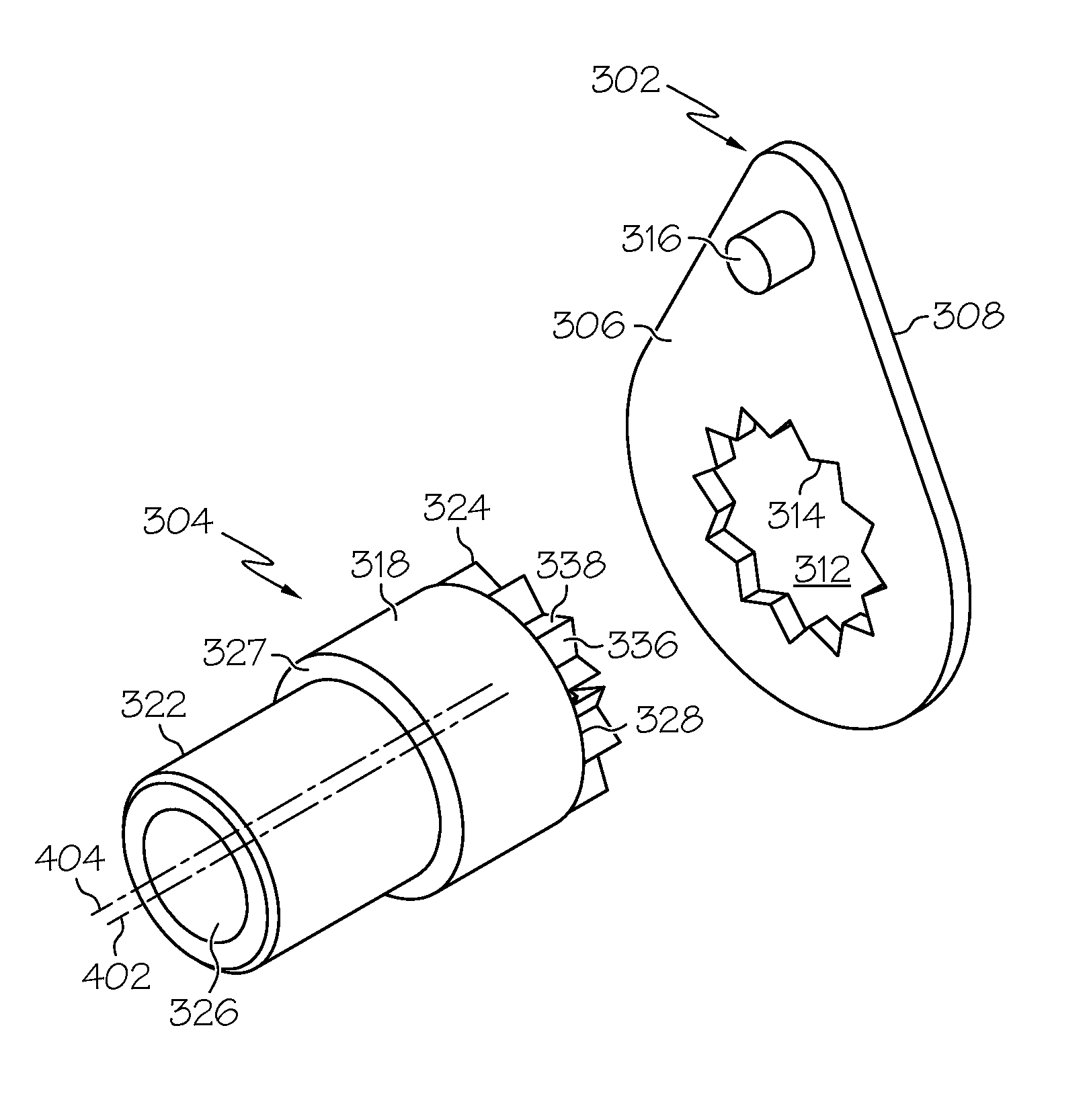
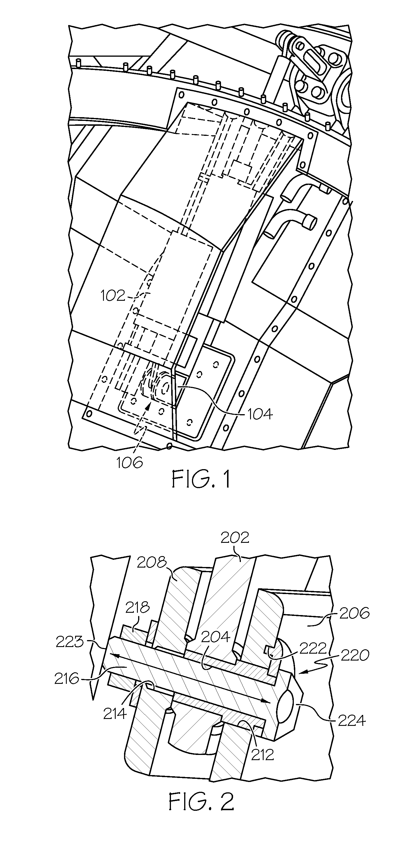
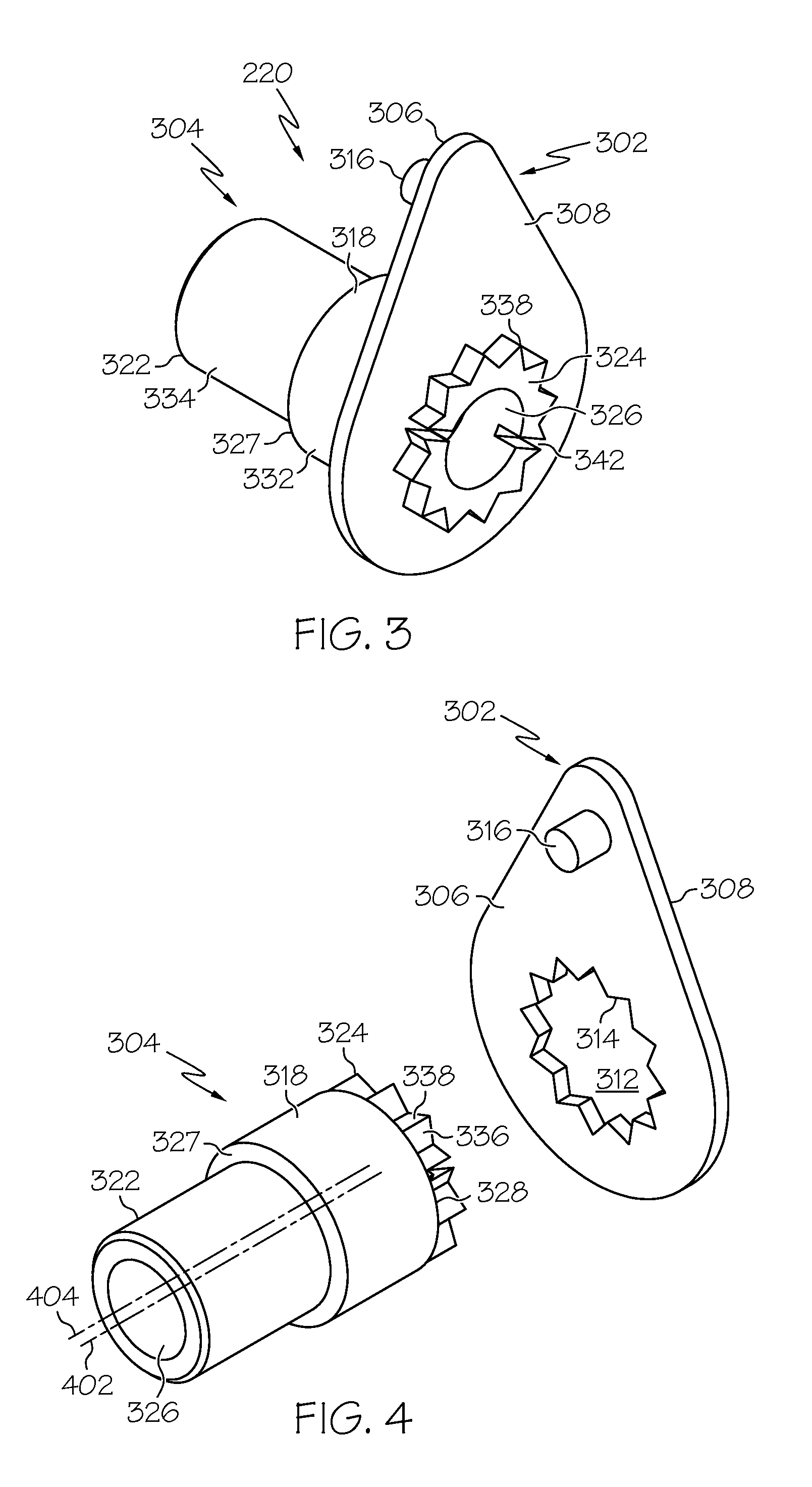
An adjustable and lockable bushing assembly includes a locking plate and a bushing. The locking plate has a bushing engagement opening that is defined by a plurality of first serrations, and a boss that extends axially therefrom. The bushing engages the locking plate and includes a concentric section, an eccentric section, a lock interface section, and an opening. The opening has a fixed diameter and extends along a longitudinal axis through the bushing. The concentric section has an outer surface that has a circumference that is concentric with the longitudinal axis. The eccentric section extends from the concentric section has an outer surface that has a circumference that is eccentric with the longitudinal axis. The lock interface section extends from the concentric section and includes an outer surface defined by a plurality of second serrations that engage the first serrations.

Description

TECHNICAL FIELD[0001]The present invention generally relates to bushings used as part of component mounting hardware, and more particularly relates to an adjustable and lockable bushing assembly.BACKGROUND[0002]Many mechanical components and mounting structures, such as those used in the aerospace industry, may be precision manufactured. Even so, these mechanical components and mounting structures still have certain manufacturing and assembly tolerances. These tolerances can impact the overall operational space envelope of the mechanical components. For example, in the context of an actuator that is configured to translate between extended and retracted positions, the manufacturing and assembly tolerances associated with the actuator and associated mounting structures and mounting hardware can impact its overall operational length.[0003]While presently known devices are available to compensate for manufacturing and assembly tolerances, these solutions can, in many instances, rely on...

Claims


Application Information

Patent Timeline
IPC IPC(8): F16L5/00F16M13/00
CPCY10T16/05F16C23/10
Inventor KOWAL, ADAMROBBINS, ROBLISTON, LAURENCEHEIN, JEFFREYDORAS, VINCENT
Owner HONEYWELL INT INC
Learn More