Path changing rotational conveyor for lightweight articles
a technology of rotating conveyors and lightweight articles, which is applied in the direction of conveyors, conveyor parts, furnaces, etc., can solve the problems of increasing economic costs, increasing the construction complexity of rotors, and relatively high installation and maintenance economic costs, and achieves easy and reversible fixed, installation or uninstallation easily and quickly, and large air flow rate
- Summary
- Abstract
- Description
- Claims
- Application Information
AI Technical Summary
Benefits of technology
Problems solved by technology
Method used
Image
Examples
first embodiment
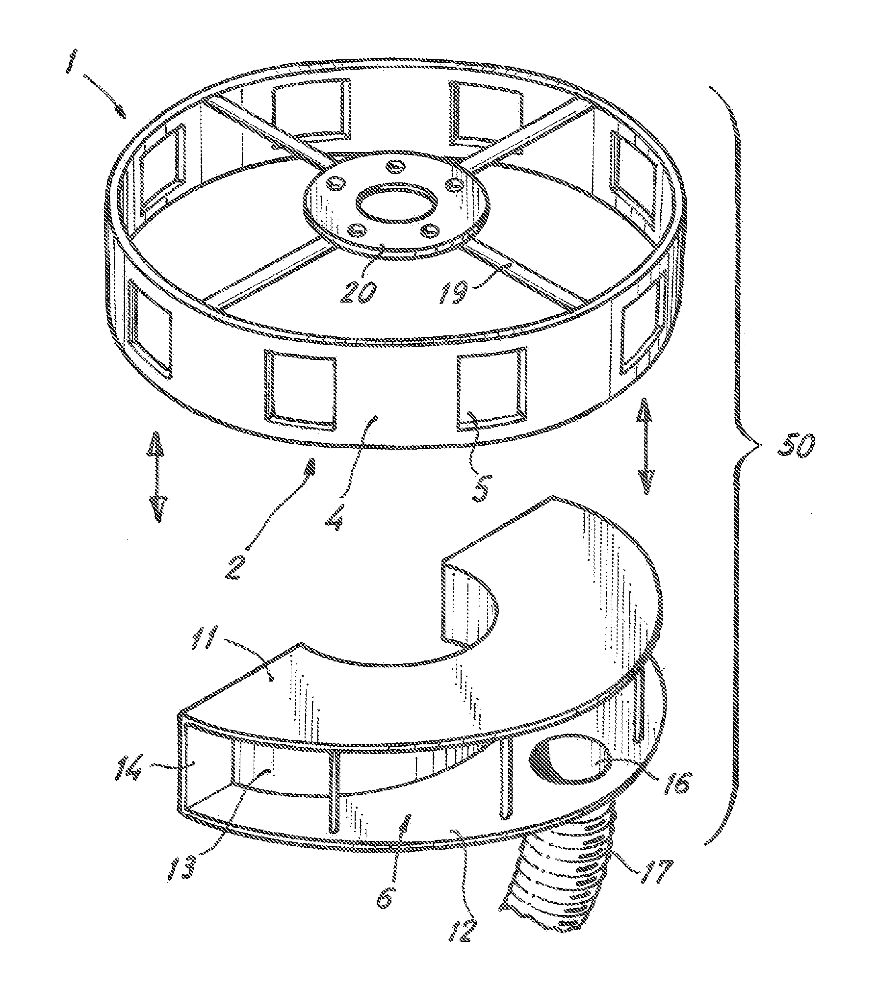
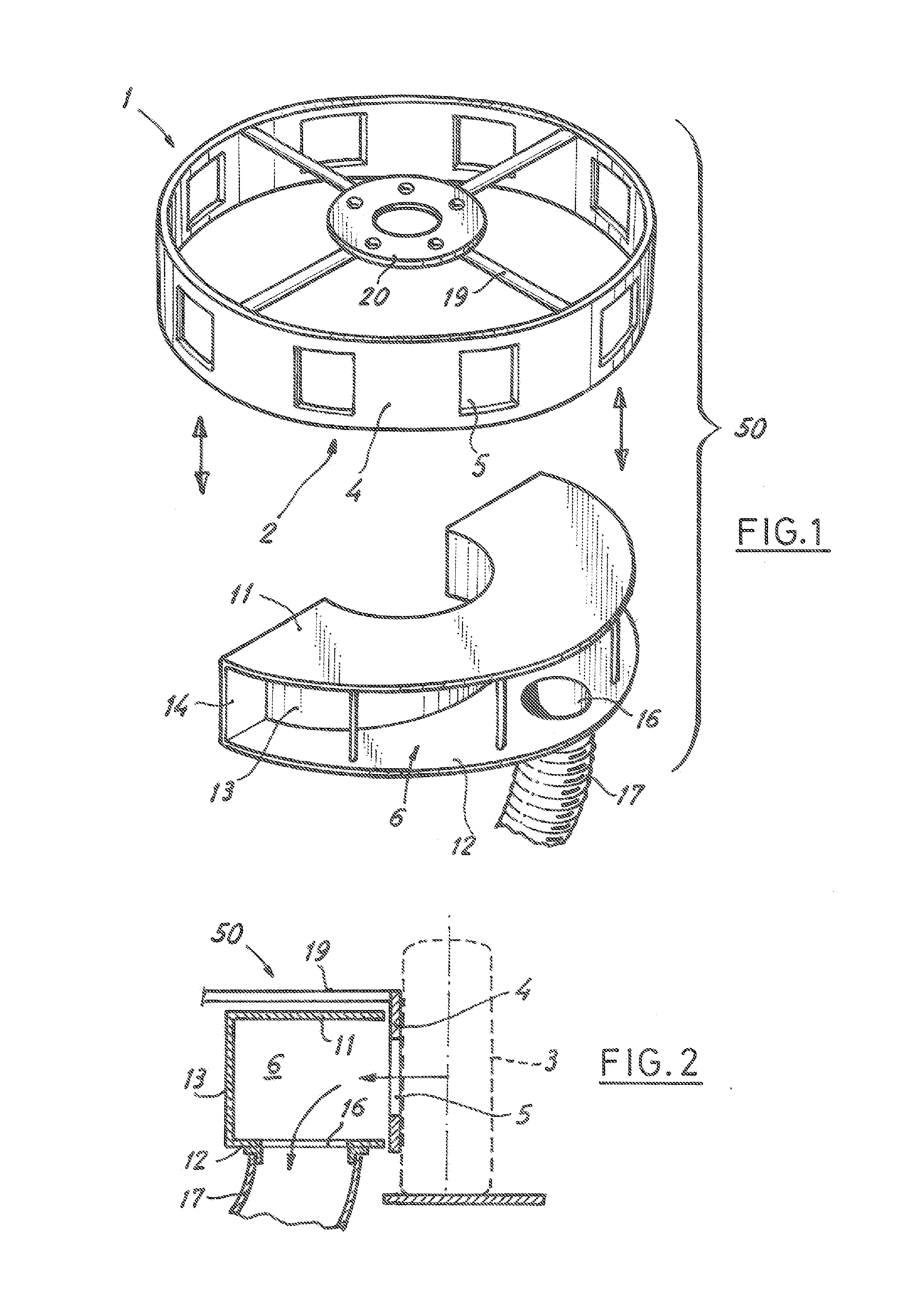
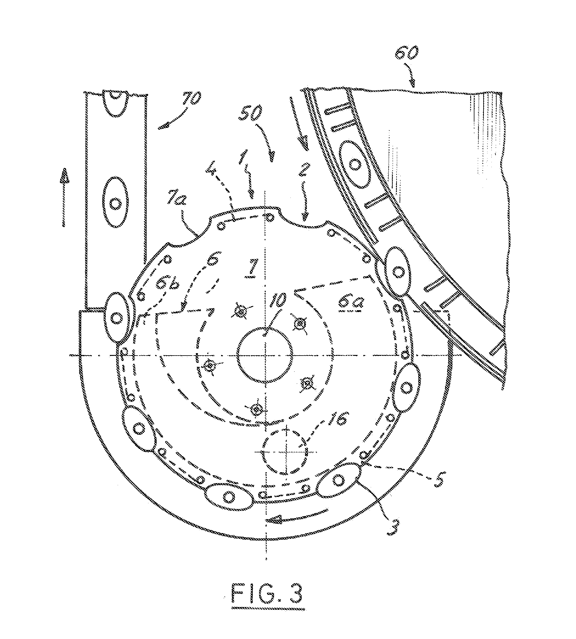
[0028]With reference first to FIGS. 1 and 2, reference number 50 generally designates a path changing rotational conveyor for lightweight articles 3 according to the present invention, taking into account that FIGS. 1 and 2 only depict two of the essential components of the rotational conveyor 50, such as a rotor 1 and a negative pressure chamber 6. The mentioned rotor 1 comprises a perimetric wall 4 in the form of a cylindrical annular wall connected to a central anchoring configuration 20 by means of radial arms 19. This anchoring configuration 20 is formed such that it can be fixed to a rotating support 9 arranged to rotate with respect to a vertical axis or together with a vertical axis 10 (similar to that shown in FIGS. 4 and 6). The rotor 1 is fixed to the rotating support 9 by reversible fixing means, such as screws or the like. Rotation means, such as an electric motor or the like, are connected to make the rotating support 9 and consequently the rotor 1 when it is fixed to ...
second embodiment
[0038]FIG. 9 shows a rotational conveyor 50 according to a variant of the second embodiment in the operating position, in which the rotor 1 is the same as that of FIG. 8 and the variant is based on the fact that the negative pressure chamber 6 lacks the upper wall 11. Thus, the negative pressure chamber 6 of FIG. 9 comprises only a lower wall 12 placed substantially at the same level as the lower plate 8, with the curved outer edge of the lower wall 12 facing and close to an inner edge of the central circular opening 8b of the lower plate 8 of the rotor 1, and side walls 13, 14 with respective upper edges facing and close to the upper plate 7 of the rotor 1. Here, the negative pressure chamber 6 is partly delimited by the upper plate 7 and the perimetric wall 4 of the rotor 1 along the predetermined circumferential arc.
[0039]In relation again to FIG. 3, the rotational conveyor 50 of the present invention is arranged such that the upstream end 6a of the negative pressure chamber 6 in...
PUM
 Abstract
Description
Claims
Application Information
 - R&D
- Intellectual Property
- Life Sciences
- Materials
- Tech Scout
- Unparalleled Data Quality
- Higher Quality Content
- 60% Fewer Hallucinations
Browse by: Latest US Patents, China's latest patents, Technical Efficacy Thesaurus, Application Domain, Technology Topic, Popular Technical Reports.
© 2025 PatSnap. All rights reserved.Legal|Privacy policy|Modern Slavery Act Transparency Statement|Sitemap|About US| Contact US: help@patsnap.com


